Components COMPONENTS ILLUSTRATION 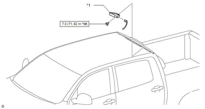
Installation INSTALLATION PROCEDURE 1. INSTALL DOOR CONTROL AND TIRE PRESSURE MONITORING SYSTEM RECEIVER ASSEMBLY (a) Attach the 2 guides to install the door control and tire pressure monitoring system receiver assembly with the bolt. Torque: 7.0 N·m {71 kgf·cm, 62 in·lbf} NOTICE:
(b) Connect the connector. 2. INSTALL ROOF HEADLINING ASSEMBLY Click here 3. CONNECT CABLE TO NEGATIVE BATTERY TERMINAL NOTICE: When disconnecting the cable, some systems need to be initialized after the cable
is reconnected (See page 4. REGISTRATION OF TRANSMITTER ID Click here 5. INSPECT TIRE PRESSURE WARNING SYSTEM Click here 6. PERFORM INITIALIZATION Click here Removal REMOVAL CAUTION / NOTICE / HINT NOTICE:
PROCEDURE 1. DISCONNECT CABLE FROM NEGATIVE BATTERY TERMINAL NOTICE: When disconnecting the cable, some systems need to be initialized after the cable
is reconnected (See page 2. REMOVE ROOF HEADLINING ASSEMBLY Click here 3. REMOVE DOOR CONTROL AND TIRE PRESSURE MONITORING SYSTEM RECEIVER ASSEMBLY 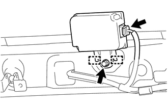
(a) Disconnect the connector. (b) Remove the bolt. (c) Detach the 2 guides and remove the door control and tire pressure monitoring system receiver assembly. NOTICE:
|
Toyota Tundra Service Manual > Rear Seat Assembly(for Crewmax Rh Side): Installation
INSTALLATION PROCEDURE 1. INSTALL REAR OUTER SEAT LEG BRACKET SUB-ASSEMBLY RH (a) Install rear outer seat leg bracket sub-assembly RH with the 2 bolts. Torque: 42 N·m {428 kgf·cm, 31 ft·lbf} 2. INSTALL REAR INNER SEAT LEG BRACKET SUB-ASSEMBLY RH (a) Install rear inner seat leg bracket sub-assembl ...


 ) after registration (See page

