DESCRIPTION |
DTC Code | DTC Detection Condition |
Trouble Area | | B1532 |
When either condition below is met:.
- The stereo component tuner assembly is not connected while the ignition switch is ON or ACC.
- Communication between the radio and display receiver assembly and the
stereo component tuner assembly is not possible when the engine is
started.
|
- No. 1 navigation wire
- Stereo component tuner assembly
- Radio and display receiver assembly
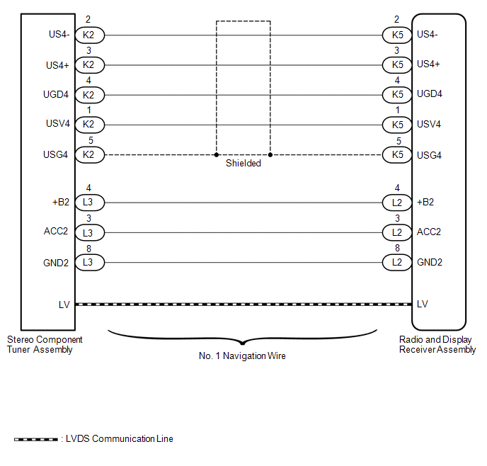
| | B156C | WIRING DIAGRAM
 CAUTION / NOTICE / HINT
NOTICE: After
replacing the stereo component tuner assembly of vehicles subscribed to
pay-type satellite radio broadcasts, XM radio ID registration is
necessary. PROCEDURE
(a) Clear the DTCs (See page
 ). ). (b) Check for DTCs (See page
). OK: No DTCs are output.
| OK |
 | USE SIMULATION METHOD TO CHECK |
|
NG |
 | |
| 2. |
CHECK HARNESS AND CONNECTOR (RADIO AND DISPLAY RECEIVER ASSEMBLY - STEREO COMPONENT TUNER ASSEMBLY) |
(a) Disconnect the K5 and L2 radio and display receiver assembly connectors.
(b) Disconnect the K2 and L3 stereo component tuner assembly connectors.
(c) Measure the resistance according to the value(s) in the table below.
Standard Resistance: |
Tester Connection | Condition |
Specified Condition | |
K5-1 (USV4) - K2-1 (USV4) |
Always | Below 1 Ω | |
K5-2 (US4-) - K2-2 (US4-) |
Always | Below 1 Ω | |
K5-3 (US4+) - K2-3 (US4+) |
Always | Below 1 Ω | |
K5-4 (UGD4) - K2-4 (UGD4) |
Always | Below 1 Ω | |
K5-5 (USG4) - K2-5 (USG4) |
Always | Below 1 Ω | |
L2-4 (+B2) - L3-4 (+B2) |
Always | Below 1 Ω | |
L2-3 (ACC2) - L3-3 (ACC2) |
Always | Below 1 Ω | |
L2-8 (GND2) - L3-8 (GND2) |
Always | Below 1 Ω | |
K5-1 (USV4) - Body ground |
Always | 10 kΩ or higher | |
K5-2 (US4-) - Body ground |
Always | 10 kΩ or higher | |
K5-3 (US4+) - Body ground |
Always | 10 kΩ or higher | |
K5-4 (UGD4) - Body ground |
Always | 10 kΩ or higher | |
K5-5 (USG4) - Body ground |
Always | 10 kΩ or higher | |
L2-4 (+B2) - Body ground |
Always | 10 kΩ or higher | |
L2-3 (ACC2) - Body ground |
Always | 10 kΩ or higher | |
L2-8 (GND2) - Body ground |
Always | 10 kΩ or higher | Result |
Result | Proceed to | |
OK | A | |
NG (for Column Shift Type) |
B | | NG (for Floor Shift Type) |
C |
| B |
| REPAIR OR REPLACE NO.1 NAVIGATION WIRE |
| C |
| REPAIR OR REPLACE NO. 1 NAVIGATION WIRE |
|
A | |
| |
| 3. |
CHECK NO. 1 NAVIGATION WIRE (LVDS COMMUNICATION LINE) |
(a) Replace the No. 1 navigation wire with a known good one.
- for Column Shift Type: See page
- for Floor Shift Type: See page
(b) Clear the DTCs (See page ). (c) Check for DTCs (See page
). OK: No DTCs are output.
| OK |
| END (NO. 1 NAVIGATION WIRE [LVDS COMMUNICATION LINE] IS DEFECTIVE) |
|
NG | |
| |
| 4. |
CHECK STEREO COMPONENT TUNER ASSEMBLY |
(a) Replace the stereo component tuner assembly with a known good one.
- for Column Shift Type: See page
- for Floor Shift Type: See page
(b) Clear the DTCs (See page ). (c) Check for DTCs (See page
). OK: No DTCs are output. Result |
Result | Proceed to | |
OK | A | |
NG (for Column Shift Type) |
B | | NG (for Floor Shift Type) |
C |
| A |
| END (STEREO COMPONENT TUNER ASSEMBLY IS DEFECTIVE) |
| B |
| REPLACE RADIO AND DISPLAY RECEIVER ASSEMBLY |
| C |
| REPLACE RADIO AND DISPLAY RECEIVER ASSEMBLY | | 

