INSPECTION PROCEDURE 1. INSPECT FRONT DOOR LOCK ASSEMBLY LH (a) Check the door lock motor. (1) Apply battery voltage to the door lock motor and check operation of the door lock motor. 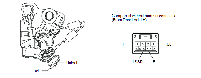
OK:
(b) Check the door lock position switch. (1) Measure the resistance according to the value(s) in the table below. Standard resistance:
(c) Check the door lock and unlock switch. (1) Measure the resistance according to the value(s) in the table below. 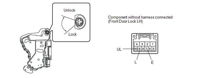
Standard resistance:
2. INSPECT FRONT DOOR LOCK ASSEMBLY RH (a) Check the door lock motor. (1) Apply battery voltage to the door lock motor and check operation of the door lock motor. 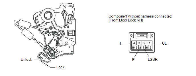
OK:
(b) Check the door lock position switch. (1) Measure the resistance according to the value(s) in the table below. Standard resistance:
|
Toyota Tundra Service Manual > Power Window Master Switch: Installation
INSTALLATION PROCEDURE 1. INSTALL POWER WINDOW REGULATOR MASTER SWITCH ASSEMBLY (a) Install the power window regulator master switch assembly with the 3 screws. 2. INSTALL FRONT UPPER ARMREST BASE PANEL LH (a) Connect the master switch connector. (b) Attach the 2 clips and 5 claws to install the fro ...


