PARTS LOCATION ILLUSTRATION 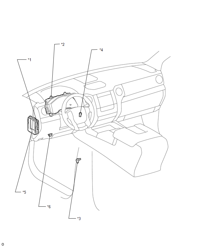
|
Toyota Tundra Service Manual > Vehicle Stability Control System: Speed Sensor Rotor Faulty (C1237)
DESCRIPTION The skid control ECU (brake actuator assembly) measures the speed of each wheel by receiving signals from each speed sensor. These signals are used for recognizing that all four wheels are operating properly. Therefore, signals from all wheels must be equal. DTC No. Detection Item DTC De ...


