DESCRIPTION
The main body ECU (multiplex network body ECU) receives switch signals from the
door control switch assembly on the driver and front passenger door and activates
the door lock motor on each door according to these signals.
WIRING DIAGRAM
w/o Jam Protection Function: 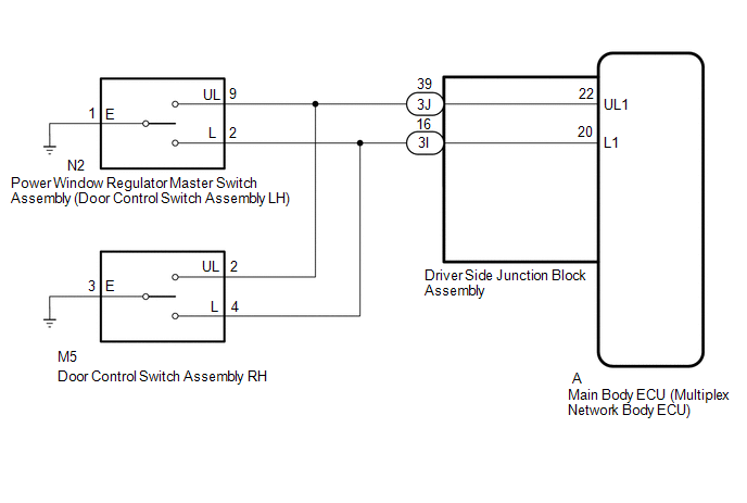 w/ Jam
Protection Function: w/ Jam
Protection Function: 
CAUTION / NOTICE / HINT
NOTICE:
- When using the Techstream with the ignition switch off, connect the Techstream
to the DLC3 and turn a courtesy light switch on and off at intervals of 1.5
seconds or less until communication between the Techstream and the vehicle begins.
Then select the vehicle type under manual mode and enter the following menus:
Body Electrical / Main Body. While using the Techstream, periodically turn a
courtesy light switch on and off at intervals of 1.5 seconds or less to maintain
communication between the Techstream and the vehicle.
- The power door lock control system uses the LIN communication system. Inspect
the communication function by following How to Proceed with Troubleshooting.
Troubleshoot the power door lock control system after confirming that the communication
systems are functioning properly.
Click here 
PROCEDURE
|
1.
|
CHECK DOOR LOCK OPERATION
|
(a) Check door lock operation.
Click here
|
Result
|
Proceed to
|
|
All doors cannot be locked by power window regulator master switch assembly
(door control switch assembly LH) (w/o Jam Protection Function)
|
A
|
|
All doors cannot be locked by power window regulator master switch assembly
(door control switch assembly LH) (w/ Jam Protection Function)
|
B
|
|
All doors cannot be locked by door control switch assembly RH
|
C
|
| B |
 |
GO TO STEP 6
|
| C |
|
GO TO STEP 7
|
| A |

|
|
|
2.
|
READ VALUE USING TECHSTREAM (Door Lock SW-Lock, Door Lock SW-Unlock)
|
(a) Connect the Techstream to the DLC3.
(b) Turn the ignition switch to ON.
(c) Turn the Techstream on.
(d) Enter the following menus: Body Electrical / Main Body / Data List.
(e) Read the Data List according to the display on the Techstream.
Main Body
|
Tester Display
|
Measurement Item/Range
|
Normal Condition
|
Diagnostic Note
|
|
Door Lock SW-Lock
|
Door control switch lock signal/ON or OFF
|
ON: Door control switch assembly LH is pushed to LOCK
OFF: Both door control switch assembly LH and RH are not pushed to LOCK
|
-
|
|
Door Lock SW-Unlock
|
Door control switch lock signal/ON or OFF
|
ON: Door control switch assembly LH is pushed to UNLOCK
OFF: Both door control switch assembly LH and RH are not pushed to UNLOCK
|
-
|
OK:
The Techstream indicates ON or OFF according to the switch operation shown in
the table.
| OK |
|
REPLACE MAIN BODY ECU (MULTIPLEX NETWORK BODY ECU)
|
| NG |
|
|
|
|
3.
|
INSPECT POWER WINDOW REGULATOR MASTER SWITCH ASSEMBLY (DOOR CONTROL SWITCH
ASSEMBLY LH)
|
(a) Remove the power window regulator master switch assembly (door control switch
assembly LH).
Click here
(b) Inspect the power window regulator master switch assembly (door control switch
assembly LH).
Click here
| NG |
|
REPLACE POWER WINDOW REGULATOR MASTER SWITCH ASSEMBLY (DOOR CONTROL SWITCH
ASSEMBLY LH)
|
| OK |
|
|
|
|
4.
|
CHECK HARNESS AND CONNECTOR (POWER WINDOW REGULATOR MASTER SWITCH ASSEMBLY
(DOOR CONTROL SWITCH ASSEMBLY LH) - MAIN BODY ECU (MULTIPLEX NETWORK BODY
ECU) AND BODY GROUND)
|
(a) Disconnect the N2 power window regulator master switch assembly (door control
switch assembly LH) connector.
(b) Disconnect the M5 door control switch assembly RH connector.
(c) Remove the main body ECU (multiplex network body ECU).
Click here
(d) Connect the driver side junction block assembly connectors.
(e) Measure the resistance according to the value(s) in the table below.
Standard Resistance:
|
Tester Connection
|
Condition
|
Specified Condition
|
|
N2-2 (L) - A-20 (L1)
|
Always
|
Below 1 Ω
|
|
N2-9 (UL) - A-22 (UL1)
|
Always
|
Below 1 Ω
|
|
N2-1 (E) - Body ground
|
Always
|
Below 1 Ω
|
|
N2-2 (L) or A-20 (L1) - Body ground
|
Always
|
10 kΩ or higher
|
|
N2-9 (UL) or A-22 (UL1) - Body ground
|
Always
|
10 kΩ or higher
|
| OK |
|
REPLACE MAIN BODY ECU (MULTIPLEX NETWORK BODY ECU)
|
| NG |
|
|
|
|
5.
|
CHECK HARNESS AND CONNECTOR (POWER WINDOW REGULATOR MASTER SWITCH ASSEMBLY
(DOOR CONTROL SWITCH ASSEMBLY LH) - DRIVER SIDE JUNCTION BLOCK ASSEMBLY
AND BODY GROUND)
|
(a) Disconnect the N2 power window regulator master switch assembly (door control
switch assembly LH) connector.
(b) Disconnect the M5 door control switch assembly RH connector.
(c) Disconnect the 3J and 3I driver side junction block assembly connectors.
(d) Measure the resistance according to the value(s) in the table below.
Standard Resistance:
|
Tester Connection
|
Condition
|
Specified Condition
|
|
N2-2 (L) - 3I-16
|
Always
|
Below 1 Ω
|
|
N2-9 (UL) - 3J-39
|
Always
|
Below 1 Ω
|
|
N2-1 (E) - Body ground
|
Always
|
Below 1 Ω
|
|
N2-2 (L) or 3I-16 - Body ground
|
Always
|
10 kΩ or higher
|
|
N2-9 (UL) or 3J-39 - Body ground
|
Always
|
10 kΩ or higher
|
| OK |
|
REPLACE DRIVER SIDE JUNCTION BLOCK ASSEMBLY
|
| NG |
|
REPAIR OR REPLACE HARNESS OR CONNECTOR
|
|
6.
|
READ VALUE USING TECHSTREAM (Door Lock Switch Status, Door Unlock Switch
Status)
|
(a) Connect the Techstream to the DLC3.
(b) Turn the ignition switch to ON.
(c) Turn the Techstream on.
(d) Enter the following menus: Body Electrical / Master Switch / Data List.
(e) According to the display on the Techstream, read the "Data List".
Master Switch
|
Tester Display
|
Measurement Item/Range
|
Normal Condition
|
Diagnostic Note
|
|
Door Lock Switch Status
|
Driver door lock switch signal/ON or OFF
|
ON: Door control switch assembly LH turned to LOCK
OFF: Door control switch assembly LH not turned
|
-
|
|
Door Unlock Switch Status
|
Driver door unlock switch signal/ON or OFF
|
ON: Door control switch assembly LH turned to UNLOCK
OFF: Door control switch assembly LH not turned
|
-
|
OK:
The display is as specified in the normal condition column.
| OK |
|
REPLACE MAIN BODY ECU (MULTIPLEX NETWORK BODY ECU)
|
| NG |
|
REPLACE POWER WINDOW REGULATOR MASTER SWITCH
|
|
7.
|
READ VALUE USING TECHSTREAM (Door Lock SW-Lock, Door Lock SW-Unlock)
|
(a) Connect the Techstream to the DLC3.
(b) Turn the ignition switch to ON.
(c) Turn the Techstream on.
(d) Enter the following menus: Body Electrical / Main Body / Data List.
(e) Read the Data List according to the display on the Techstream.
Main Body
|
Tester Display
|
Measurement Item/Range
|
Normal Condition
|
Diagnostic Note
|
|
Door Lock SW-Lock
|
Door control switch lock signal/ON or OFF
|
ON: Door control switch assembly RH is pushed to LOCK
OFF: Both door control switch assembly LH and RH are not pushed to LOCK
|
-
|
|
Door Lock SW-Unlock
|
Door control switch lock signal/ON or OFF
|
ON: Door control switch assembly RH is pushed to UNLOCK
OFF: Both door control switch assembly LH and RH are not pushed to UNLOCK
|
-
|
OK:
The Techstream indicates ON or OFF according to the switch operation shown in
the table.
| OK |
|
REPLACE MAIN BODY ECU (MULTIPLEX NETWORK BODY ECU)
|
| NG |
|
|
|
|
8.
|
INSPECT DOOR CONTROL SWITCH ASSEMBLY RH
|
(a) Remove the door control switch assembly RH.
Click here
(b) Inspect the door control switch assembly RH.
Click here
| NG |
|
REPLACE DOOR CONTROL SWITCH ASSEMBLY RH
|
| OK |
|
|
|
|
9.
|
CHECK HARNESS AND CONNECTOR (DOOR CONTROL SWITCH ASSEMBLY RH - DRIVER
SIDE JUNCTION BLOCK ASSEMBLY AND BODY GROUND)
|
(a) Disconnect the M5 door control switch assembly RH connector.
(b) Disconnect the N2 power window regulator master switch assembly (door control
switch assembly LH) connector.
(c) Remove the main body ECU (multiplex network body ECU).
Click here
(d) Connect the driver side junction block assembly connectors.
(e) Measure the resistance according to the value(s) in the table below.
Standard Resistance:
|
Tester Connection
|
Condition
|
Specified Condition
|
|
M5-4 (L) - A-20 (L1)
|
Always
|
Below 1 Ω
|
|
M5-2 (UL) - A-22 (UL1)
|
Always
|
Below 1 Ω
|
|
M5-3 (E) - Body ground
|
Always
|
Below 1 Ω
|
|
M5-4 (L) or A-20 (L1) - Body ground
|
Always
|
10 kΩ or higher
|
|
M5-2 (UL) or A-22 (UL1) - Body ground
|
Always
|
10 kΩ or higher
|
| OK |
|
REPLACE MAIN BODY ECU (MULTIPLEX NETWORK BODY ECU)
|
| NG |
|
|
|
|
10.
|
CHECK HARNESS AND CONNECTOR (DOOR CONTROL SWITCH ASSEMBLY RH - DRIVER
SIDE JUNCTION BLOCK ASSEMBLY AND BODY GROUND)
|
(a) Disconnect the M5 door control switch assembly RH connector.
(b) Disconnect the N2 power window regulator master switch assembly (door control
switch assembly LH) connector.
(c) Disconnect the 3J and 3I driver side junction block assembly connectors.
(d) Measure the resistance according to the value(s) in the table below.
Standard Resistance:
|
Tester Connection
|
Condition
|
Specified Condition
|
|
M5-4 (L) - 3I-16
|
Always
|
Below 1 Ω
|
|
M5-2 (UL) - 3J-39
|
Always
|
Below 1 Ω
|
|
M5-3 (E) - Body ground
|
Always
|
Below 1 Ω
|
|
M5-4 (L) or 3I-16 - Body ground
|
Always
|
10 kΩ or higher
|
|
M5-2 (UL) or 3J-39 - Body ground
|
Always
|
10 kΩ or higher
|
| OK |
|
REPLACE DRIVER SIDE JUNCTION BLOCK ASSEMBLY
|
| NG |
|
REPAIR OR REPLACE HARNESS OR CONNECTOR
|
| 

