Toyota Tundra Service Manual: Data Signal Circuit between Radio Receiver and Stereo Jack Adapter

Toyota Tundra Service Manual / Audio, Visual, Telematics / Audio / Video / Audio And Visual System / Data Signal Circuit between Radio Receiver and Stereo Jack Adapter

DESCRIPTION

The No. 1 stereo jack adapter assembly sends the sound data signal or image data signal from a device to the radio and display receiver assembly via this circuit.

WIRING DIAGRAM
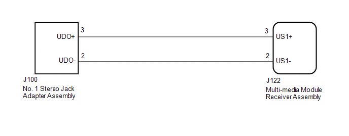
PROCEDURE

1.

CHECK HARNESS AND CONNECTOR (RADIO AND DISPLAY RECEIVER ASSEMBLY - NO. 1 STEREO JACK ADAPTER ASSEMBLY)

(a) Disconnect the J122 radio and display receiver assembly connector.

(b) Disconnect the J100 No. 1 stereo jack adapter assembly connector.

(c) Measure the resistance according to the value(s) in the table below.

Standard Resistance:

Tester Connection

Condition

Specified Condition

J122-2 (US1-) - J100-2 (UDO-)

Always

Below 1 Ω

J122-3 (US1+) - J100-3 (UDO+)

Always

Below 1 Ω

J122-2 (US1-) - Body ground

Always

10 kΩ or higher

J122-3 (US1+) - Body ground

Always

10 kΩ or higher

OK

PROCEED TO NEXT SUSPECTED AREA SHOWN IN PROBLEM SYMPTOMS TABLE

NG

REPAIR OR REPLACE HARNESS OR CONNECTOR

    Data List / Active Test

    Diagnostic Trouble Code Chart

    See More:

    Toyota Tundra Service Manual > 1ur-fe Emission Control: Egr Cooler
    ComponentsCOMPONENTS ILLUSTRATION InstallationINSTALLATION PROCEDURE 1. INSTALL NO. 2 EGR PIPE SUB-ASSEMBLY (a) Install a new gasket and the No. 2 EGR pipe with the 2 bolts. Torque: 10 N·m {102 kgf·cm, 7 ft·lbf} NOTICE: Make sure the gasket's claws are not caught between the No. 2 EGR pipe and E ...

    Toyota Tundra Owners Manual

    Toyota Tundra Service Manual

    © 2025 Copyright www.ttundra.com
    0.0369