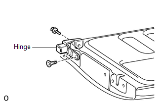
INSTALLATION PROCEDURE 1. INSTALL TAIL GATE MALE HINGE SUB-ASSEMBLY LH
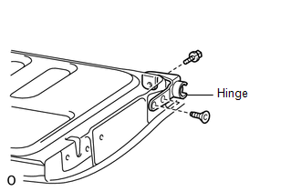
2. INSTALL TAIL GATE MALE HINGE SUB-ASSEMBLY RH (a) Using a T40 "TORX" wrench, install the tail gate lock male hinge sub-assembly with the 2 screws. Torque: 29 N·m {296 kgf·cm, 21 ft·lbf} 3. INSTALL TAIL GATE HINGE ASSEMBLY LH
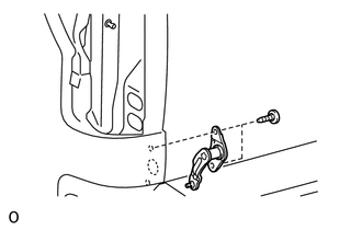
(b) Install the bolt to the tail gate. Torque: 18 N·m {184 kgf·cm, 13 ft·lbf} 4. INSTALL TAIL GATE HINGE ASSEMBLY RH
(b) Install the bolt to the tail gate. Torque: 18 N·m {184 kgf·cm, 13 ft·lbf} 5. INSTALL REAR BODY TAIL GATE ASSEMBLY
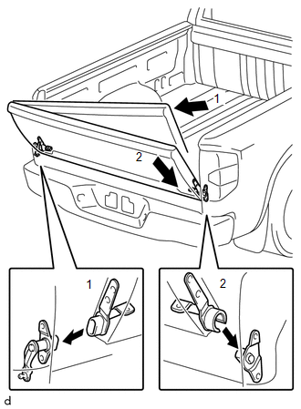
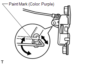
(b) Move the tail in the direction of arrow 2 in the illustration to connect the tail gate assembly hinge RH and install the tail gate. 6. INSTALL TAIL GATE STAY ASSEMBLY
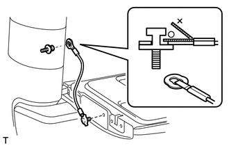
(b) Install the tail gate cable and deck side shaft to the body. Torque: 14 N·m {143 kgf·cm, 10 ft·lbf} HINT: Use the same procedures described above to the other side. 7. INSTALL SIDE GATE SUPPORT SUB-ASSEMBLY LH
8. INSTALL REAR COMBINATION LIGHT ASSEMBLY LH
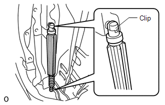
9. INSTALL TAIL GATE LOCK STRIKER (a) Using a T40 "TORX" wrench, install the 2 tail gate lock strikers with the 4 screws. Torque: 13 N·m {133 kgf·cm, 10 ft·lbf} 10. INSTALL TAIL GATE LOCK KEY CYLINDER (a) Install the tail gate lock cylinder with the snap ring. 11. INSTALL TAIL GATE HANDLE ASSEMBLY
12. INSTALL TELEVISION CAMERA ASSEMBLY (w/ Rear View Monitor System)
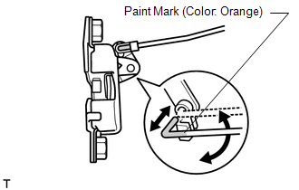
13. INSTALL TAIL GATE LOCK CONTROL LINK LH
14. INSTALL TAIL GATE LOCK CONTROL LINK RH
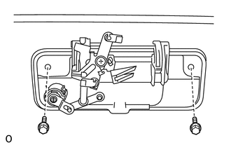
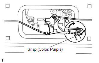
15. INSTALL TAIL GATE LOCK ASSEMBLY LH (a) Using a T40 "TORX" wrench, install the tail gate lock with the 2 screws. Torque: 13 N·m {133 kgf·cm, 10 ft·lbf}
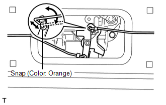
16. INSTALL TAIL GATE LOCK ASSEMBLY RH (a) Using a T40 "TORX" wrench, install the tail gate lock with the 2 screws. Torque: 13 N·m {133 kgf·cm, 10 ft·lbf}
17. INSTALL TAIL GATE SERVICE HOLE COVER (a) Using a T30 "TORX" wrench, install the service hole cover with the 8 screws. 18. INSTALL TAIL GATE PROTECTOR
19. CHECK CONNECTION OF TELEVISION CAMERA ASSEMBLY (w/ Rear View Monitor System)
|
Toyota Tundra Service Manual > Navigation System: Cursor or Map Rotates when Vehicle Stopped
PROCEDURE 1. CHECK CONDITION (a) Check with the customer if the vehicle has been turned by a turntable. OK: Vehicle has not been turned by a turntable. HINT: If the vehicle is turned on a turntable with the ignition switch to ON, the system may store the angular velocity. As a result, the vehicle po ...