Toyota Tundra Service Manual: Parts Location

PARTS LOCATION

ILLUSTRATION
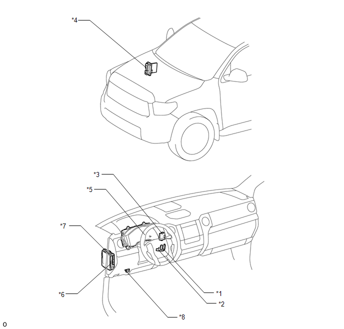
*1

UNLOCK WARNING SWITCH ASSEMBLY

*2

TRANSPONDER KEY COIL

*3

TRANSPONDER KEY ECU ASSEMBLY

*4

ECM

*5

COMBINATION METER ASSEMBLY (SECURITY INDICATOR LIGHT)

*6

MAIN BODY ECU (MULTIPLEX NETWORK BODY ECU)

*7

DRIVER SIDE JUNCTION BLOCK ASSEMBLY

- ECU-B NO.1 FUSE

- ECU-IG2 NO.3 FUSE

- IG2-NO.2 RELAY

*8

DLC3

    Key Cannot be Registered

    Precaution

    See More:

    Toyota Tundra Service Manual > Can Communication System: Check Bus 3 Line for Short to GND
    DESCRIPTION There may be a short circuit between one of the CAN bus wires and +B when no resistance exists between terminal 6 (CA3H) of the central gateway ECU (network gateway ECU) and terminal 4 (CG) of the DLC3, or terminal 21 (CA3L) of the central gateway ECU (network gateway ECU) and terminal 4 ...

    Toyota Tundra Owners Manual

    Toyota Tundra Service Manual

    © 2026 Copyright www.ttundra.com
    0.0335