REMOVAL CAUTION / NOTICE / HINT HINT:
PROCEDURE 1. REMOVE LOWER NO. 1 SIDE PANEL MOULDING LH HINT: When removing the lower No. 1 side panel moulding LH, heat the vehicle body and lower No. 1 side panel moulding LH using a heat light. Standard:
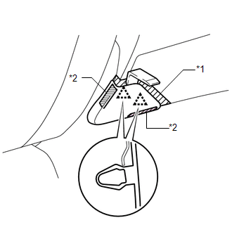
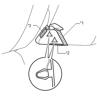
NOTICE: Do not heat the vehicle body and lower No. 1 side panel moulding LH excessively. (a) for Double Cab: (1) Using a heat light, heat the vehicle body and lower No. 1 side panel moulding LH. (2) Put protective tape around the lower No. 1 side panel moulding LH.
(b) for CrewMax: (1) Using a heat light, heat the vehicle body and lower No. 1 side panel moulding LH. (2) Put protective tape around the lower No. 1 side panel moulding LH.
2. REMOVE REAR BODY NO. 3 PROTECTOR LH HINT: When removing the rear body No. 3 protector LH, heat the vehicle body and rear body No. 3 protector LH using a heat light. Standard:
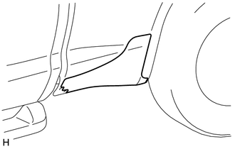
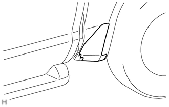
NOTICE: Do not heat the vehicle body or rear body No. 3 protector LH excessively. (a) for Double Cab: (1) Using a heat light, heat the vehicle body and rear body No. 3 protector LH.
(b) for CrewMax: (1) Using a heat light, heat the vehicle body and rear body No. 3 protector LH.
|
Toyota Tundra Service Manual > Front Propeller Shaft Assembly: Inspection
INSPECTION PROCEDURE 1. INSPECT FRONT PROPELLER SHAFT ASSEMBLY (a) Check that the propeller shaft is not damaged or deformed. If necessary, replace the propeller shaft. (b) Using a dial indicator, check the propeller shaft runout. Maximum runout: 0.61 mm (0.0240 in.) 2. INSPECT UNIVERSAL JOINT SPIDE ...