DISASSEMBLY PROCEDURE 1. REMOVE BOX BOTTOM MAT 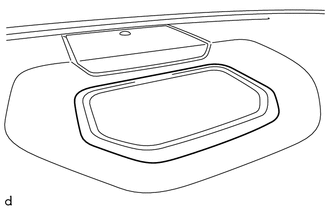
(a) Remove the box bottom mat. 2. REMOVE NO. 1 SPEAKER HOLE COVER (a) Apply protective tape as shown in the illustration. 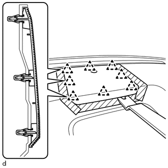
(b) Using a moulding remover B, detach the 8 clips and remove the No. 1 speaker hole cover. (c) Disconnect the connector. 3. REMOVE FRONT NO. 4 SPEAKER ASSEMBLY (w/ Front Center Speaker) Click here 4. REMOVE NO. 1 INSTRUMENT PANEL PIN HINT: Use the same procedure to remove the No. 1 instrument panel pin on the other side.
5. REMOVE DEFROSTER NOZZLE ASSEMBLY 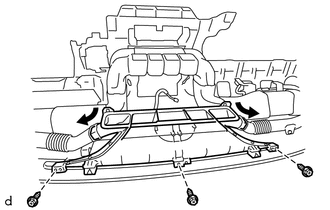
(a) Disconnect the No. 1 side defroster nozzle duct and No. 2 side defroster nozzle duct from the defroster nozzle assembly. (b) Remove the 3 screws <E> and defroster nozzle assembly. 6. REMOVE NO. 2 HEATER TO REGISTER DUCT (a) Remove the 8 screws <E> and No. 2 heater to register duct. 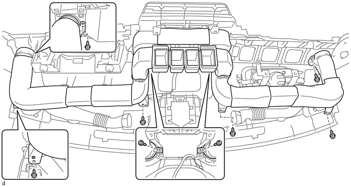
7. REMOVE NO. 1 SIDE DEFROSTER NOZZLE DUCT
8. REMOVE NO. 2 SIDE DEFROSTER NOZZLE DUCT
9. REMOVE INSTRUMENT CLUSTER FINISH PANEL REINFORCEMENT 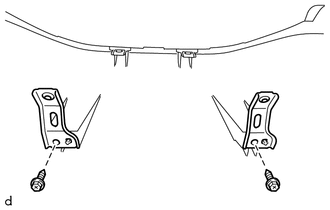
(a) Remove the 2 screws <F> and 2 instrument cluster finish panel reinforcements. 10. REMOVE NAVIGATION ANTENNA ASSEMBLY (w/ Navigation System) Click here 11. REMOVE FRONT PASSENGER AIRBAG ASSEMBLY Click here |
Toyota Tundra Service Manual > Touch Select 2-4 And High-low System: Transfer Shift Motor Control Circuit Circuit Open (P17A8,P17A9)
DESCRIPTION This DTC is detected when an open circuit or short to ground is detected in the transfer shift motor drive circuit. DTC Code DTC Detection Condition Diagnosis Condition Malfunction Status Malfunction Time Other Trouble Area P17A8 Ignition switch ON (when transfer shift motor is not opera ...