Components COMPONENTS ILLUSTRATION 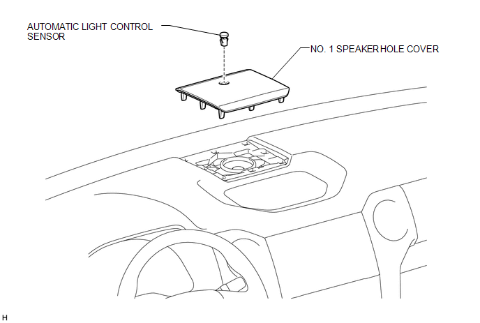
Installation INSTALLATION PROCEDURE 1. INSTALL AUTOMATIC LIGHT CONTROL SENSOR (a) Attach the 2 claws to install the automatic light control sensor. 2. INSTALL NO. 1 SPEAKER HOLE COVER (a) Connect the connector. (b) Attach the 8 clips to install the No. 1 speaker hole cover. On-vehicle Inspection ON-VEHICLE INSPECTION PROCEDURE 1. INSPECT AUTOMATIC LIGHT CONTROL SENSOR 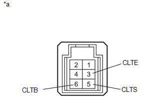
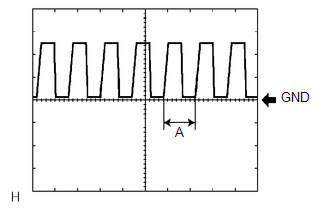
(a) Measure the voltage according to the value(s) in the table below. Standard Voltage:
(b) Measure the resistance according to the value(s) in the table below. Standard Resistance:
(c) Reconnect the automatic light control sensor connector.
Removal REMOVAL PROCEDURE 1. REMOVE NO. 1 SPEAKER HOLE COVER 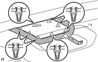
(a) Put protective tape around the No. 1 speaker hole cover. Text in Illustration
(b) Using moulding remover B, detach the 8 clips. (c) Disconnect the connector and remove the No. 1 speaker hole cover. 2. REMOVE AUTOMATIC LIGHT CONTROL SENSOR 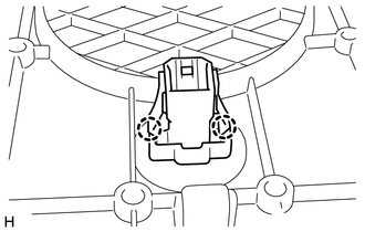
(a) Detach the 2 claws and remove the automatic light control sensor. |
Toyota Tundra Service Manual > Audio And Visual System: Confirm Cellular Phone Functionality
PROCEDURE 1. CHECK THE CUSTOMER'S CELLULAR PHONE COMPATIBILITY (a) Go to TIS "Bluetooth" Compatibility Portal and check if the cellular phone is compatible. Result Result Proceed to Cellular phone is compatible A Cellular phone is not compatible B HINT:It is important to check the cellular phone com ...