INSTALLATION PROCEDURE 1. INSTALL AIR CONDITIONING CONTROL ASSEMBLY (HAZARD WARNING SWITCH) 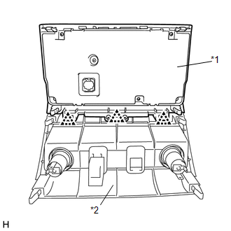
(a) Attach the 3 clips to connect the air conditioning control assembly (hazard warning switch) and center lower instrument panel finish panel. Text in Illustration
(b) Put protective tape around the air conditioning control assembly (hazard warning switch). (c) Connect each connector. (d) Attach the 8 clips, 2 claws and guide to install the air conditioning control assembly (hazard warning switch) with the center lower instrument panel finish panel. 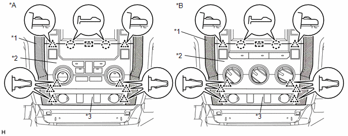 Text in Illustration Text in Illustration
2. INSTALL CENTER LOWER INSTRUMENT COVER (for Column Shift Type)
3. INSTALL FRONT CONSOLE BOX (for Floor Shift Type)
4. INSTALL REAR CONSOLE BOX ASSEMBLY (for Floor Shift Type)
5. INSTALL CONSOLE BOX CARPET (for Floor Shift Type)
6. INSTALL REAR CONSOLE END PANEL SUB-ASSEMBLY (for Floor Shift Type)
7. INSTALL UPPER CONSOLE PANEL SUB-ASSEMBLY (for Floor Shift Type)
8. INSTALL UPPER REAR CONSOLE PANEL SUB-ASSEMBLY (for Floor Shift Type)
9. INSTALL SHIFT LEVER KNOB SUB-ASSEMBLY (for Floor Shift Type)
|
Toyota Tundra Service Manual > Sliding Roof Housing(for Crewmax): Disassembly
DISASSEMBLY PROCEDURE 1. REMOVE SLIDING ROOF DRIVE GEAR SUB-ASSEMBLY (a) Remove the 2 bolts, room light bracket and drive gear. 2. REMOVE SUNSHADE TRIM SUB-ASSEMBLY (a) Remove the 2 screws. (b) Detach the 4 claws and remove the sliding roof piece LH and RH. (c) Slide and remove the trim. 3. REMOVE S ...


