INSPECTION PROCEDURE 1. INSPECT HEADLIGHT DIMMER SWITCH ASSEMBLY 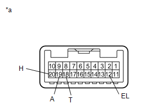
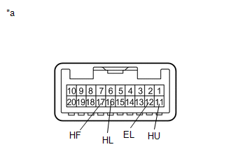
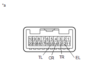
(a) Inspect the light control switch. (1) Measure the resistance according to the value(s) in the table below. Standard Resistance:
If the result is not as specified, replace the headlight dimmer switch assembly. Text in Illustration
|
Toyota Tundra Service Manual > Lighting System: Door Mirror Foot Light Circuit
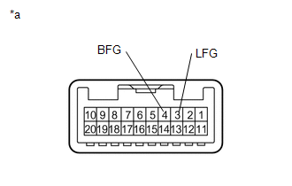
DESCRIPTION The outer mirror control ECU assembly controls the outer rear view mirror assembly (footwell lights). WIRING DIAGRAM PROCEDURE 1. CHECK FOOTWELL LIGHTS (a) Check the illumination of each footwell lights. Result Proceed to Footwell light LH does not illuminate. A Footwell light RH does no ...