DESCRIPTION The main body ECU (multiplex network body ECU) detects the condition of the parking brake switch assembly. WIRING DIAGRAM 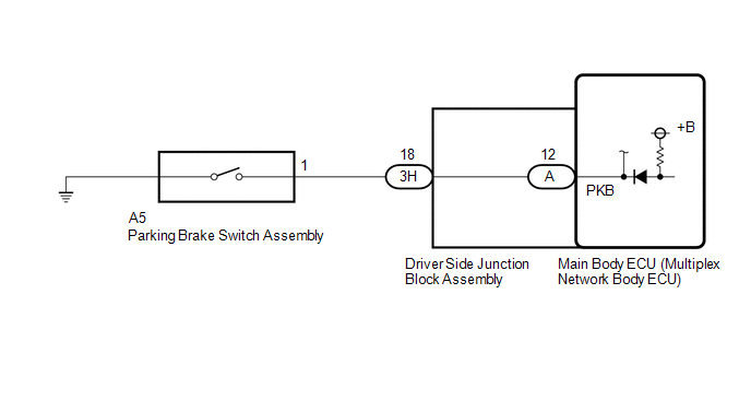
PROCEDURE
(a) Using the Techstream, read the Data List. Click here
OK: Normal condition listed above are displayed.
(a) Remove the parking brake switch assembly. Click here (b) Inspect the parking brake switch assembly. Click here
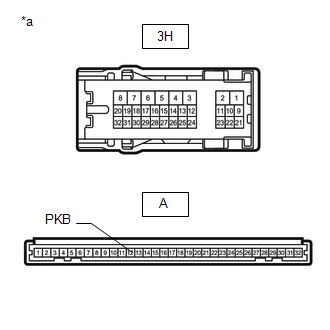
(a) Disconnect the 3H driver side junction block assembly connector. (b) Disconnect the A5 parking brake switch assembly connector. (c) Measure the resistance according to the value(s) in the table below. Standard Resistance:
(b) Remove the main body ECU (multiplex network body ECU) from the driver side junction block assembly. Click here (c) Measure the resistance according to the value(s) in the table below. Standard Resistance:
|
Toyota Tundra Service Manual > Fuel Pump: Installation
INSTALLATION CAUTION / NOTICE / HINT HINT: Perform "Inspection After Repairs" after replacing the fuel pump. Click here PROCEDURE 1. INSTALL FUEL SUCTION WITH PUMP AND GAUGE TUBE ASSEMBLY (a) Apply a light coat of gasoline to a new gasket, and install it to the fuel tank assembly. (b) Align the prot ...