Components COMPONENTS ILLUSTRATION 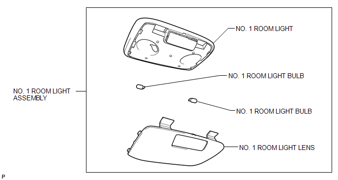
Disassembly DISASSEMBLY PROCEDURE 1. REMOVE NO. 1 ROOM LIGHT BULB 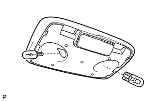
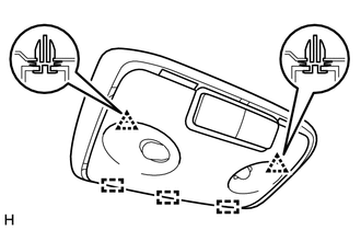
(a) Remove the 2 No. 1 room light bulbs from the No. 1 room light. Installation INSTALLATION PROCEDURE 1. INSTALL NO. 1 ROOM LIGHT ASSEMBLY (a) Attach the 3 guides and 2 clips to install the No. 1 room light assembly. (b) Attach the 2 guides and 4 claws to install the No. 1 room light lens. Reassembly REASSEMBLY PROCEDURE 1. INSTALL NO. 1 ROOM LIGHT BULB (a) Install the 2 No. 1 room light bulbs to the No. 1 room light. Removal REMOVAL PROCEDURE 1. REMOVE NO. 1 ROOM LIGHT ASSEMBLY 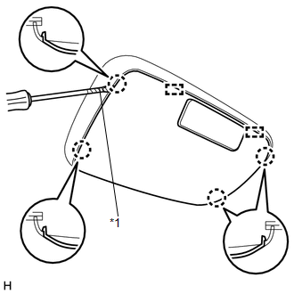
(a) Using a screwdriver, detach the 4 claws and 2 guides and remove the No. 1 room light lens. Text in Illustration
|
Toyota Tundra Service Manual > Front Power Seat Control System(w/ Memory): Wireless Transmitter Memory Function does not Operate
DESCRIPTION With the ignition switch off and the driver door closed, pressing the manual lock or unlock switch on the power window regulator master switch assembly while holding a seat memory switch (M1 switch or M2 switch) will register the transmitter recognition code into the seat memory switch t ...