DESCRIPTION This circuit provides power to the stereo component amplifier assembly. WIRING DIAGRAM 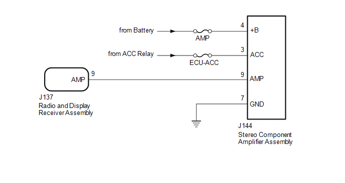 CAUTION / NOTICE / HINT NOTICE: Inspect the fuses for circuits related to this system before performing the following procedure. PROCEDURE
(b) Measure the resistance according to the value(s) in the table below. Standard Resistance:
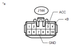
(c) Measure the voltage according to the value(s) in the table below. Standard Voltage:
(a) Disconnect the J144 stereo component amplifier assembly connector. (b) Disconnect the J137 radio and display receiver assembly connector. (c) Measure the resistance according to the value(s) in the table below. Standard Resistance:
|
Toyota Tundra Service Manual > Cylinder Head Gasket(for Bank 2): Installation
INSTALLATION CAUTION / NOTICE / HINT HINT: Perform "Inspection After Repairs" after replacing the cylinder head sub-assembly RH (See page ). PROCEDURE 1. INSPECT CYLINDER HEAD SET BOLT 2. INSPECT CYLINDER HEAD SUB-ASSEMBLY RH 3. INSTALL CYLINDER HEAD GASKET RH (a) Check the piston protrusions for ea ...