DESCRIPTION Audio function: This circuit is necessary for the automatic sound levelizer (ASL) built into the radio and display receiver assembly.
ASL function: Speed signals are received from the combination meter assembly and used for the ASL.
The
ASL function automatically adjusts the sound volume in order to
maintain clear audio sound even when vehicle noise increases (as vehicle
noise increases, the volume is turned up, etc.).
HINT:
- A voltage of 12 V or 5 V is output from each ECU connected to the
combination meter assembly, and then input to the combination meter
assembly. The signal is changed to a pulse signal at the transistor in
the combination meter assembly. Each ECU controls its respective systems
based on the pulse signal.
- If a short occurs in any of the ECU or in the wire harness connected to an ECU, related components will not operate normally.
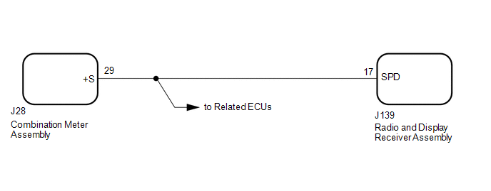
WIRING DIAGRAM
 PROCEDURE
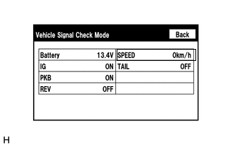
| (a) Enter the "Vehicle Signal Check Mode" screen. [Refer to Check Vehicle Signal Check Mode in Operation Check (See page
 )] )] |
|
(b) While driving the vehicle, compare the value of "SPEED" to the reading on the speedometer.
(1) Check if these readings are almost equal. OK: Vehicle speed displayed on the "Vehicle Signal Check Mode" screen is almost the same as the reading on the speedometer.
| OK |
 | PROCEED TO NEXT SUSPECTED AREA SHOWN IN PROBLEM SYMPTOMS TABLE |
|
NG |
 | |
| 2. |
CHECK HARNESS AND CONNECTOR (RADIO AND DISPLAY RECEIVER ASSEMBLY - COMBINATION METER ASSEMBLY) |
(a) Disconnect the J139 radio and display receiver assembly connector.
(b) Disconnect the J28 combination meter assembly connector. (c) Measure the resistance according to the value(s) in the table below.
Standard Resistance: |
Tester Connection | Condition |
Specified Condition | |
J139-17 (SPD) - J28-29 (+S) |
Always | Below 1 Ω | |
J139-17 (SPD) - Body ground |
Always | 10 kΩ or higher |
| NG |
| REPAIR OR REPLACE HARNESS OR CONNECTOR |
|
OK | |
| |
| 3. |
INSPECT COMBINATION METER ASSEMBLY (SPEED SIGNAL) |
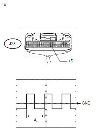
| (a) Check the input waveform. (1) Remove the combination meter assembly with the connector(s) still connected.
(2) Connect an oscilloscope to terminal J28-29 (+S) and body ground.
(3) Turn the ignition switch to ON. (4) Check the signal waveform according to the condition(s) in the table below. Measurement Condition |
Item | Condition | |
Terminal No. (Symbol) |
J28-29 (+S) - Body ground | |
Tool setting | 5 V/DIV., 20 ms./DIV. | |
Condition | Being driven at approximately 20 km/h (12 mph) |
OK: The waveform displayed is as shown in the illustration.
HINT: When the system is functioning normally, one wheel revolution generates 4 pulses.
As the vehicle speed increases, the width indicated by (A) in the illustration narrows. Text in Illustration |
*a | Component with harness connected
(Combination Meter Assembly) | Result |
Result | Proceed to | |
OK (for Column Shift Type) |
A | | OK (for Floor Shift Type) |
B | | NG |
C | | |
| A |
| REPLACE RADIO AND DISPLAY RECEIVER ASSEMBLY |
| B |
| REPLACE RADIO AND DISPLAY RECEIVER ASSEMBLY |
| C |
| GO TO METER / GAUGE SYSTEM | |