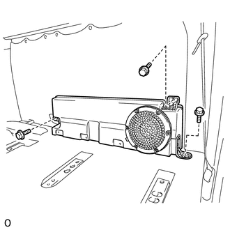
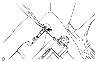
Components COMPONENTS ILLUSTRATION 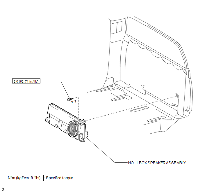 Inspection INSPECTION PROCEDURE 1. INSPECT NO. 1 BOX SPEAKER ASSEMBLY 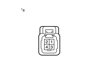 (a) Measure the resistance according to the value(s) in the table below. Standard resistance:
If the result is not as specified, replace the No. 1 box speaker assembly. Text in Illustration
Installation INSTALLATION PROCEDURE 1. INSTALL NO. 1 BOX SPEAKER ASSEMBLY (a) Connect the connector.
2. INSTALL REAR SEAT ASSEMBLY RH (See page
3. INSTALL REAR SEAT ASSEMBLY LH (See page Removal REMOVAL PROCEDURE 1. REMOVE REAR SEAT ASSEMBLY LH (See page
2. REMOVE REAR SEAT ASSEMBLY RH (See page
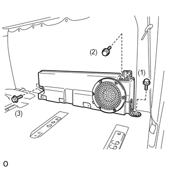
3. REMOVE NO. 1 BOX SPEAKER ASSEMBLY
|
Toyota Tundra Service Manual > Air Conditioning System(for Automatic Air Conditioning System): Air Inlet Damper Control Servo Motor Circuit (B1442/42)
DESCRIPTION The air inlet damper servo motor sends pulse signals to inform the air conditioning amplifier of the damper position. The air conditioning amplifier activates the motor (normal, reverse) based on the signals to move the air inlet damper to any position, which controls the intake air sett ...

 )
) )
)