INSPECTION
PROCEDURE
1. INSPECT BACK DOOR POWER WINDOW REGULATOR MOTOR
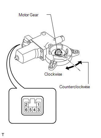
(a) Inspect the operation of the power window regulator motor.
(1) Check that the motor operates smoothly when battery voltage is applied to
terminals 1 and 2 as follows.
OK:
|
Measurement Condition
|
Specified Condition
|
|
Battery positive (+) → 2
Battery negative (-) → 1
|
Motor gear rotates counterclockwise
|
|
Battery positive (+) → 1
Battery negative (-) → 2
|
Motor gear rotates clockwise
|
If the result is not as specified, replace the motor.
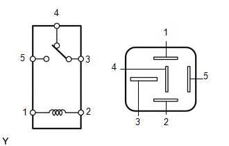
2. INSPECT NO. 1 BACK POWER WINDOW RELAY (except 3UR-FBE)
(a) Remove the power window relay from the engine room relay block.
|
(b) Measure the resistance according to the value(s) in the table below.
Standard resistance:
|
Tester Connection
|
Condition
|
Specified Condition
|
|
3 - 4
|
When battery voltage is not applied between terminals 1 and 2
|
Below 1 Ω
|
|
When battery voltage is applied between terminals 1 and 2
|
10 kΩ or higher
|
|
3 - 5
|
When battery voltage is not applied between terminals 1 and 2
|
10 kΩ or higher
|
|
When battery voltage is applied between terminals 1 and 2
|
Below 1 Ω
|
If the result is not as specified, replace the relay.
|
|
3. INSPECT NO. 2 BACK POWER WINDOW RELAY
(a) Remove the power window relay from the engine room relay block.
|
(b) Measure the resistance according to the value(s) in the table below.
Standard resistance:
|
Tester Connection
|
Condition
|
Specified Condition
|
|
3 - 4
|
When battery voltage is not applied between terminals 1 and 2
|
Below 1 Ω
|
|
When battery voltage is applied between terminals 1 and 2
|
10 kΩ or higher
|
|
3 - 5
|
When battery voltage is not applied between terminals 1 and 2
|
10 kΩ or higher
|
|
When battery voltage is applied between terminals 1 and 2
|
Below 1 Ω
|
If the result is not as specified, replace the relay.
|
|
4. INSPECT NO. 3 BACK POWER WINDOW RELAY (for 3UR-FBE)
(a) Remove the power window relay from the engine room relay block.
|
(b) Measure the resistance according to the value(s) in the table below.
Standard resistance:
|
Tester Connection
|
Condition
|
Specified Condition
|
|
3 - 4
|
When battery voltage is not applied between terminals 1 and 2
|
Below 1 Ω
|
|
When battery voltage is applied between terminals 1 and 2
|
10 kΩ or higher
|
|
3 - 5
|
When battery voltage is not applied between terminals 1 and 2
|
10 kΩ or higher
|
|
When battery voltage is applied between terminals 1 and 2
|
Below 1 Ω
|
If the result is not as specified, replace the relay.
|
|
|