ON-VEHICLE INSPECTION
PROCEDURE
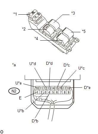
1. CHECK POWER WINDOW REGULATOR MASTER SWITCH ASSEMBLY (w/o Jam Protection Function)
|
*1
|
Window Lock Switch
|
|
*2
|
Driver Switch
|
|
*3
|
Front Passenger Switch
|
|
*4
|
Rear LH Switch
|
|
*5
|
Rear RH Switch
|
|
*a
|
Component with harness connected
(Power Window Regulator Master Switch assembly)
|
|
*b
|
for Driver Side
|
|
*c
|
Front Passenger Side
|
|
*d
|
for Rear LH Side
|
|
*e
|
for Rear RH Side
|
(a) for Double Cab:
(1) Remove the power window regulator master switch assembly.
Click here 
(2) Reconnect the switch connector.
(3) Measure the voltage according to the value(s) in the table below.
Standard Voltage:
for Driver Switch:
|
Tester Connection
|
Switch Condition
|
Specified Condition
|
|
N2-3 (U) - N2-1 (E)
|
Ignition switch ON, driver side door power window regulator switch OFF
→ UP
|
Below 1 V → 11 to 14 V
|
|
N2-4 (D) - N2-1 (E)
|
Ignition switch ON, driver side door power window regulator switch OFF
→ DOWN
|
|
N2-4 (D) - N2-1 (E)
|
Ignition switch ON, driver side door glass fully closed → power window
AUTO DOWN operation → driver side door glass fully open
|
Below 1 V → 11 to 14 V → Below 1 V
|
for Front Passenger Switch:
|
Tester Connection
|
Switch Condition
|
Specified Condition
|
|
N2-16 (U) - N2-1 (E)
|
Ignition switch ON, front passenger side door power window regulator
switch OFF → UP
|
Below 1 V → 11 to 14 V
|
|
N2-15 (D) - N2-1 (E)
|
Ignition switch ON, front passenger side door power window regulator
switch OFF → DOWN
|
for Rear Switch LH:
|
Tester Connection
|
Switch Condition
|
Specified Condition
|
|
N2-12 (U) - N2-1 (E)
|
Ignition switch ON, rear LH side door power window regulator switch OFF
→ UP
|
Below 1 V → 11 to 14 V
|
|
N2-13 (D) - N2-1 (E)
|
Ignition switch ON, rear LH side door power window regulator switch OFF
→ DOWN
|
for Rear Switch RH:
|
Tester Connection
|
Switch Condition
|
Specified Condition
|
|
N2-10 (U) - N2-1 (E)
|
Ignition switch ON, rear RH side door power window regulator switch OFF
→ UP
|
Below 1 V → 11 to 14 V
|
|
N2-18 (D) - N2-1 (E)
|
Ignition switch ON, rear RH side door power window regulator switch OFF
→ DOWN
|
If the result is not as specified, replace the power window regulator master
switch assembly.
(b) for CrewMax:
(1) Remove the power window regulator master switch assembly.
Click here
(2) Reconnect the switch connector.
(3) Measure the voltage according to the value(s) in the table below.
Standard Voltage:
for Driver Switch:
|
Tester Connection
|
Switch Condition
|
Specified Condition
|
|
N2-3 (U) - N2-1 (E)
|
Ignition switch ON, driver side door power window regulator switch OFF
→ UP
|
Below 1 V → 11 to 14 V
|
|
N2-4 (D) - N2-1 (E)
|
Ignition switch ON, driver side door power window regulator switch OFF
→ DOWN
|
|
N2-4 (D) - N2-1 (E)
|
Ignition switch ON, driver side door glass fully closed → power window
AUTO DOWN operation → driver side door glass fully open
|
Below 1 V → 11 to 14 V → Below 1 V
|
for Front Passenger Switch:
|
Tester Connection
|
Switch Condition
|
Specified Condition
|
|
N2-16 (U) - N2-1 (E)
|
Ignition switch ON, front passenger side door power window regulator
switch OFF → UP
|
Below 1 V → 11 to 14 V
|
|
N2-15 (D) - N2-1 (E)
|
Ignition switch ON, front passenger side door power window regulator
switch OFF → DOWN
|
for Rear LH Switch:
|
Tester Connection
|
Switch Condition
|
Specified Condition
|
|
N2-12 (U) - N2-1 (E)
|
Ignition switch ON, rear LH side door power window regulator switch OFF
→ UP
|
Below 1 V → 11 to 14 V
|
|
N2-13 (D) - N2-1 (E)
|
Ignition switch ON, rear LH side door power window regulator switch OFF
→ DOWN
|
for Rear RH Switch:
|
Tester Connection
|
Switch Condition
|
Specified Condition
|
|
N2-10 (U) - N2-1 (E)
|
Ignition switch ON, rear RH side door power window regulator switch OFF
→ UP
|
Below 1 V → 11 to 14 V
|
|
N2-18 (D) - N2-1 (E)
|
Ignition switch ON, rear RH side door power window regulator switch OFF
→ DOWN
|
If the result is not as specified, replace the power window regulator master
switch assembly.
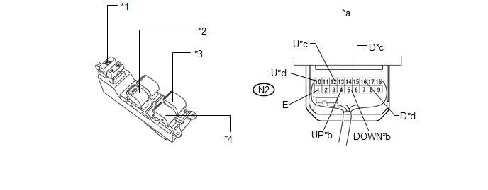
2. CHECK POWER WINDOW REGULATOR MASTER SWITCH ASSEMBLY (w/ Jam Protection Function)
 Text in Illustration Text in Illustration
|
*1
|
Window Lock Switch
|
*2
|
Driver Switch
|
|
*3
|
Rear RH Switch
|
*4
|
Rear LH Switch
|
|
*a
|
Component with harness connected
(Master Switch Assembly)
|
*b
|
for Driver Side
|
|
*c
|
for Rear LH Side
|
*d
|
for Rear RH Side
|
(a) Remove the power window regulator master switch assembly.
Click here
(b) Reconnect the switch connector.
(c) Measure the voltage according to the value(s) in the table below.
Standard Voltage:
for Driver Switch:
|
Tester Connection
|
Switch Condition
|
Specified Condition
|
|
N2-4 (UP) - N2-1 (E)
|
Ignition switch ON, driver side door power window regulator switch OFF
→ UP
|
Below 1 V → 11 to 14 V
|
|
N2-4 (UP) - N2-1 (E)
|
Ignition switch ON, driver side door glass fully closed → power window
AUTO UP operation → driver side door glass fully open
|
|
N2-5 (DOWN) - N2-1 (E)
|
Ignition switch ON, driver side door power window regulator switch OFF
→ DOWN
|
|
N2-5 (DOWN) - N2-1 (E)
|
Ignition switch ON, driver side door glass fully closed → power window
AUTO DOWN operation → driver side door glass fully open
|
Below 1 V → 11 to 14 V → Below 1 V
|
for Rear LH Switch:
|
Tester Connection
|
Switch Condition
|
Specified Condition
|
|
N2-12 (U) - N2-1 (E)
|
Ignition switch ON, rear LH side door power window regulator switch OFF
→ UP
|
Below 1 V → 11 to 14 V
|
|
N2-15 (D) - N2-1 (E)
|
Ignition switch ON, rear LH side door power window regulator switch OFF
→ DOWN
|
for Rear RH Switch:
|
Tester Connection
|
Switch Condition
|
Specified Condition
|
|
N2-10 (U) - N2-1 (E)
|
Ignition switch ON, rear RH side door power window regulator switch OFF
→ UP
|
Below 1 V → 11 to 14 V
|
|
N2-16 (D) - N2-1 (E)
|
Ignition switch ON, rear RH side door power window regulator switch OFF
→ DOWN
|
If the result is not as specified, replace the power window regulator master
switch assembly. |


