Components COMPONENTS ILLUSTRATION  Inspection INSPECTION PROCEDURE 1. INSPECT REAR NO. 1 SPEAKER ASSEMBLY (for Standard) 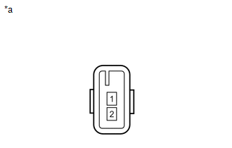 (a) Measure the resistance according to the value(s) in the table below. Standard resistance:
If the result is not as specified, replace the rear No. 1 speaker assembly. Text in Illustration
2. INSPECT REAR NO. 1 SPEAKER ASSEMBLY (for 7 Speakers) (a) Measure the resistance according to the value(s) in the table below. Standard resistance:
If the result is not as specified, replace the rear No. 1 speaker assembly. Text in Illustration
Installation INSTALLATION CAUTION / NOTICE / HINT HINT:
PROCEDURE 1. INSTALL REAR NO. 1 SPEAKER ASSEMBLY (a) Connect the connector. 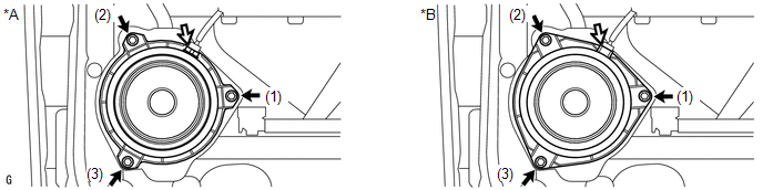 Text in Illustration Text in Illustration
(b) Install the rear No. 1 speaker assembly with the 3 screws. NOTICE: Do not touch the cone part of the speaker. HINT: Install the screws in the order shown in the illustration. 2. INSTALL REAR DOOR TRIM BOARD SUB-ASSEMBLY LH
3. INSTALL REAR DOOR ARMREST COVER LH 4. INSTALL REAR UPPER DOOR ARMREST BASE PANEL LH
5. INSTALL REAR DOOR INSIDE HANDLE BEZEL PLUG LH 6. INSTALL REAR DOOR FRAME GARNISH LH Removal REMOVAL CAUTION / NOTICE / HINT HINT:
PROCEDURE 1. REMOVE REAR DOOR FRAME GARNISH LH 2. REMOVE REAR DOOR INSIDE HANDLE BEZEL PLUG LH 3. REMOVE REAR UPPER DOOR ARMREST BASE PANEL LH 4. REMOVE REAR DOOR ARMREST COVER LH 5. REMOVE REAR DOOR TRIM BOARD SUB-ASSEMBLY LH
6. REMOVE REAR NO. 1 SPEAKER ASSEMBLY (a) Remove the 3 screws. 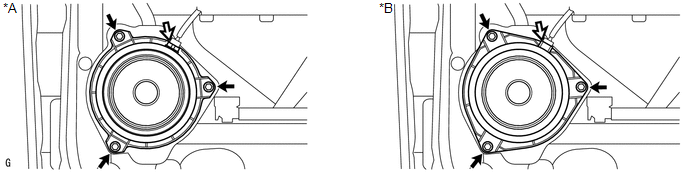 Text in Illustration Text in Illustration
NOTICE: Do not touch the cone part of the speaker. (b) Disconnect the connector and remove the rear No. 1 speaker assembly. |
Toyota Tundra Service Manual > Blind Spot Monitor System: Destination Information Undefined (C1AB8)
DESCRIPTION This DTC is stored when correct destination information is not sent from the main body ECU (multiplex network body ECU) and destination information cannot be confirmed after a blind spot monitor sensor has been replaced. DTC No. DTC Detection Condition Trouble Area C1AB8 The blind spot m ...


