DESCRIPTION This circuit includes the parking brake switch assembly and navigation receiver assembly. WIRING DIAGRAM 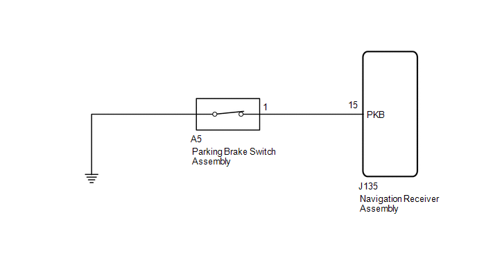 PROCEDURE
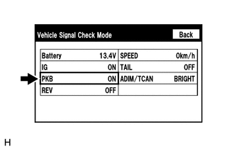
(b) Check that the display changes between ON and OFF according to the parking brake operation. OK:
HINT: This display is updated once per second. As a result, it is normal for the display to lag behind the actual parking brake operation.
(a) Disconnect the J135 navigation receiver assembly connector. (b) Disconnect the A5 parking brake switch assembly connector. (c) Measure the resistance according to the value(s) in the table below. Standard Resistance:
(a) Remove the parking brake switch assembly (See page
(b) Inspect the parking brake switch assembly (See page
|
Toyota Tundra Service Manual > Instrument Panel Safety Pad(for Floor Shift Type): Reassembly
REASSEMBLY CAUTION / NOTICE / HINT HINT: A bolt without a torque specification is shown in the standard bolt chart (See page ). PROCEDURE 1. INSTALL FRONT PASSENGER AIRBAG ASSEMBLY 2. INSTALL NAVIGATION ANTENNA ASSEMBLY (w/ Navigation System) 3. INSTALL INSTRUMENT CLUSTER FINISH PANEL REINFORCEMENT ...

 ).
).