DESCRIPTION The navigation receiver assembly receives a reverse signal from the park/neutral position switch assembly. WIRING DIAGRAM 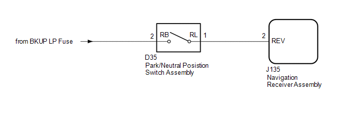 CAUTION / NOTICE / HINT NOTICE: Inspect the fuses for circuits related to this system before performing the following inspection procedure. PROCEDURE
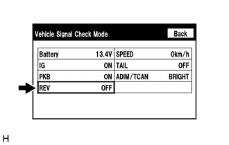
(b) Check that the display changes between ON and OFF according to the shift lever position. OK:
HINT: This display is updated once per second. As a result, it is normal for the display to lag behind the actual shift lever position.
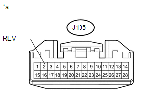 (a) Disconnect the navigation receiver assembly connector. (b) Measure the voltage according to the value(s) in the table below. Standard Voltage:
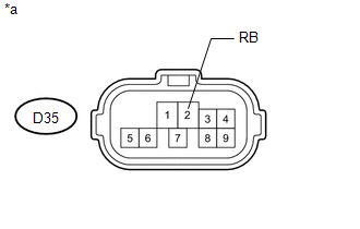
(a) Disconnect the J135 navigation receiver assembly connector. (b) Disconnect the D35 park/neutral position switch assembly connector. (c) Measure the resistance according to the value(s) in the table below. Standard Resistance:
(b) Measure the voltage according to the value(s) in the table below. Standard Voltage:
HINT: If replacing the park/neutral position switch assembly, refer to the procedures below.
|
Toyota Tundra Service Manual > Meter / Gauge System: Fuel Sender Open Detected (B1500)
DESCRIPTION This DTC is output when the combination meter detects the fuel sender gauge malfunction via the CAN. DTC Code DTC Detection Condition Trouble Area B1500 When combination meter detects fuel sender gauge malfunction Harness or connector Combination meter Fuel sender gauge Fuel suction with ...

 )].
)].