Toyota Tundra Service Manual: Sound Signal Circuit between Navigation Receiver Assembly and Stereo Component Amplifier

Toyota Tundra Service Manual / Audio, Visual, Telematics / Navigation / Multi Info Display / Navigation System / Sound Signal Circuit between Navigation Receiver Assembly and Stereo Component Amplifier

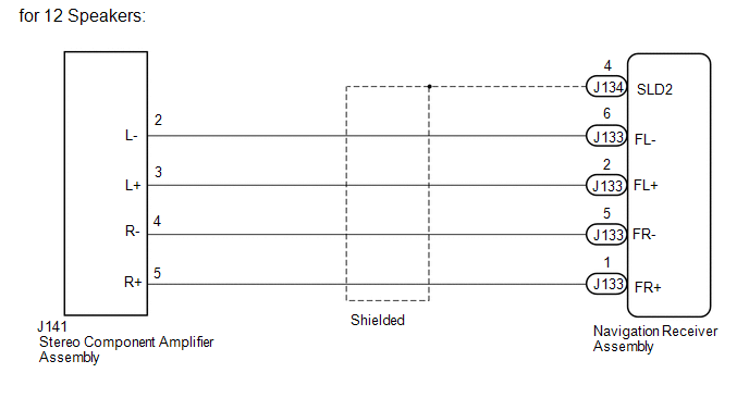
DESCRIPTION

The navigation receiver assembly sends a sound signal to the stereo component amplifier assembly via this circuit.

The sound signal that has been sent is amplified by the stereo component amplifier assembly, and then is sent to the speakers.

WIRING DIAGRAM
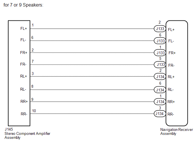
PROCEDURE

1.

CHECK HARNESS AND CONNECTOR (NAVIGATION RECEIVER ASSEMBLY - STEREO COMPONENT AMPLIFIER ASSEMBLY)

(a) for 7 or 9 Speakers:

(1) Disconnect the J134 and J133 navigation receiver assembly connectors.

(2) Disconnect the J145 stereo component amplifier assembly connector.

(3) Measure the resistance according to the value(s) in the table below.

Standard Resistance:

Tester Connection

Condition

Specified Condition

J133-2 (FL+) - J145-1 (FL+)

Always

Below 1 Ω

J133-6 (FL-) - J145-6 (FL-)

Always

Below 1 Ω

J133-1 (FR+) - J145-2 (FR+)

Always

Below 1 Ω

J133-5 (FR-) - J145-7 (FR-)

Always

Below 1 Ω

J134-2 (RL+) - J145-3 (RL+)

Always

Below 1 Ω

J134-6 (RL-) - J145-8 (RL-)

Always

Below 1 Ω

J134-1 (RR+) - J145-9 (RR+)

Always

Below 1 Ω

J134-3 (RR-) - J145-10 (RR-)

Always

Below 1 Ω

J133-2 (FL+) - Body ground

Always

10 kΩ or higher

J133-6 (FL-) - Body ground

Always

10 kΩ or higher

J133-1 (FR+) - Body ground

Always

10 kΩ or higher

J133-5 (FR-) - Body ground

Always

10 kΩ or higher

J134-2 (RL+) - Body ground

Always

10 kΩ or higher

J134-6 (RL-) - Body ground

Always

10 kΩ or higher

J134-1 (RR+) - Body ground

Always

10 kΩ or higher

J134-3 (RR-) - Body ground

Always

10 kΩ or higher

(b) for 12 Speakers:

(1) Disconnect the J134 and J133 navigation receiver assembly connectors.

(2) Disconnect the J141 stereo component amplifier assembly connector.

(3) Measure the resistance according to the value(s) in the table below.

Standard Resistance:

Tester Connection

Condition

Specified Condition

J133-6 (FL-) - J141-2 (L-)

Always

Below 1 Ω

J133-2 (FL+) - J141-3 (L+)

Always

Below 1 Ω

J133-5 (FR-) - J141-4 (R-)

Always

Below 1 Ω

J133-1 (FR+) - J141-5 (R+)

Always

Below 1 Ω

J133-6 (FL-) - Body ground

Always

10 kΩ or higher

J133-2 (FL+) - Body ground

Always

10 kΩ or higher

J133-5 (FR-) - Body ground

Always

10 kΩ or higher

J133-1 (FR+) - Body ground

Always

10 kΩ or higher

J134-4 (SLD2) - Body ground

Always

10 kΩ or higher

OK

PROCEED TO NEXT SUSPECTED AREA SHOWN IN PROBLEM SYMPTOMS TABLE

NG

REPAIR OR REPLACE HARNESS OR CONNECTOR

    Sound Quality is Bad Only when Disc is Played (Volume is Too Low)

    Sound Signal Circuit between Navigation Receiver Assembly and Stereo Jack Adapter

    See More:

    Toyota Tundra Service Manual > Air Conditioning System(for Manual Air Conditioning System): System Diagram
    SYSTEM DIAGRAM Communication table Sender Receiver Signal Line Air Conditioning Control Assembly Air Conditioning Amplifier Air conditioning control signal LIN ECM Air Conditioning Amplifier Engine speed Engine coolant temperature signal CAN ...

    Toyota Tundra Owners Manual

    Toyota Tundra Service Manual

    © 2024 Copyright www.ttundra.com
    0.016