DESCRIPTION This circuit sends an operation signal from the steering pad switch assembly to the navigation receiver assembly. If there is an open in the circuit, the audio system cannot be operated using the steering pad switch assembly. If there is a short in the circuit, the same condition as when a switch is continuously depressed occurs. Therefore, the navigation receiver assembly cannot be operated using the steering pad switch assembly, and also the navigation receiver assembly itself cannot function. WIRING DIAGRAM 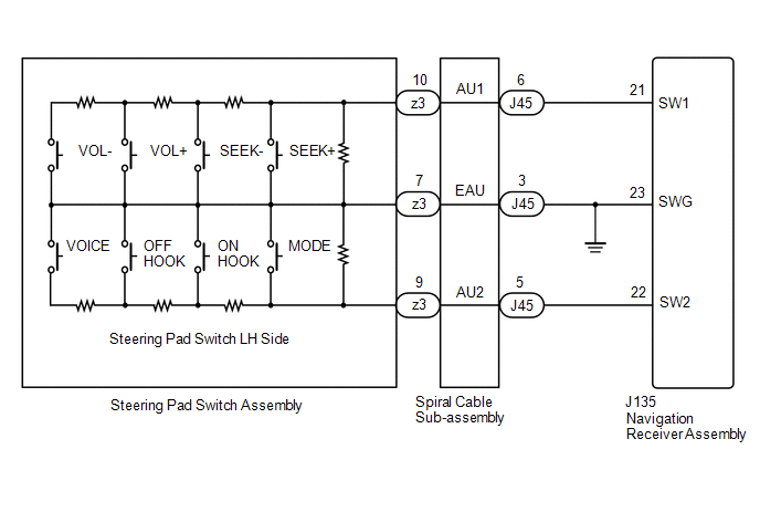 CAUTION / NOTICE / HINT NOTICE:
PROCEDURE
(a) Remove the steering pad switch assembly (See page
(b) Inspect the steering pad switch assembly (See page
(a) Remove the spiral cable sub-assembly (See page
(b) Inspect the spiral cable sub-assembly (See page
(a) Disconnect the J135 navigation receiver assembly connector. (b) Disconnect the J45 spiral cable sub-assembly connector. (c) Measure the resistance according to the value(s) in the table below. Standard Resistance:
|
Toyota Tundra Service Manual > Sfi System: Camshaft Position "A" - Timing Over-Advanced or System Performance (Bank 1) (P0011,P0012,P0021,P0022)
DESCRIPTION The VVT system includes the ECM, Oil Control Valve (OCV) and VVT controller. The ECM sends a target duty-cycle control signal to the OCV. This control signal regulates the oil pressure supplied to the VVT controller. Camshaft timing control is performed according to engine operating cond ...

 ).
).


