|
Terminal No. (Symbol) | Wiring Color |
Terminal Description | Condition |
Specified Condition |
|
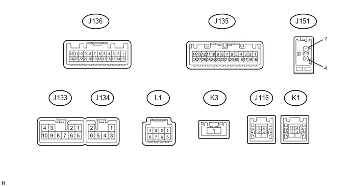
J133-1 (FR+) - J133-7 (GND1) |
LA-LG - BR*1 W - BR*2 | Sound signal (Front right) |
Audio system playing |
A waveform synchronized with sound is output |
|
J133-2 (FL+) - J133-7 (GND1) |
LA-P - BR*1 G - BR*2 | Sound signal (Front left) |
Audio system playing |
A waveform synchronized with sound is output |
|
J133-3 (ACC1) - J133-7 (GND1) |
GR - BR | Power source (ACC) |
Ignition switch off | Below 1 V |
|
Ignition switch ACC | 11 to 14 V |
|
J133-4 (+B1) - J133-7 (GND1) |
LA-SB - BR | Power source (+B) |
Always | 11 to 14 V |
|
J133-5 (FR-) - J133-7 (GND1) |
LA-L - BR*1 R - BR*2 | Sound signal (Front right) |
Audio system playing |
A waveform synchronized with sound is output |
|
J133-6 (FL-) - J133-7 (GND1) |
LA-V - BR*1 B - BR*2 | Sound signal (Front left) |
Audio system playing |
A waveform synchronized with sound is output |
|
J133-7 (GND1) - Body ground |
BR - Body ground | Ground |
Always | Below 1 Ω |
|
J133-9 (AMP) - J133-7 (GND1)*1 |
G - BR | Power source of stereo component amplifier |
Audio system playing |
11 to 14 V |
|
J133-10 (ILL+) - J133-7 (GND1) |
P - BR | Illumination signal |
Light control switch off |
Below 1 V |
| Light control switch in tail or head position |
11 to 14 V |
|
J134-1 (RR+) - J133-7 (GND1)*1 |
LA-R - BR | Sound signal (Rear right) |
Audio system playing |
A waveform synchronized with sound is output |
|
J134-2 (RL+) - J133-7 (GND1) |
LA-B - BR*1 W - BR*2 | Sound signal (Rear left) |
Audio system playing |
A waveform synchronized with sound is output |
|
J134-3 (RR-) - J133-7 (GND1)*1 |
LA-W - BR | Sound signal (Rear right) |
Audio system playing |
A waveform synchronized with sound is output |
|
J134-4 (SLD2) - J133-7 (GND1)*2 |
Shielded - BR | Shield ground |
Always | Below 1 Ω |
|
J134-5 (ILL-) - J133-7 (GND1) |
BE - BR | Illumination signal |
Light control switch off |
Below 1 V |
| Light control switch in tail or head position |
Pulse generation |
|
J134-6 (RL-) - J133-7 (GND1) |
LA-Y - BR*1 B - BR*2 | Sound signal (Rear left) |
Audio system playing |
A waveform synchronized with sound is output |
|
J135-1 (IG) - J133-7 (GND1) |
BE - BR | Power source (IG) |
Ignition switch off | Below 1 V |
|
Ignition switch ON | 11 to 14 |
|
J135-2 (REV) - J133-7 (GND1) |
Y - BR | Reverse signal |
See "Vehicle Signal Check Mode" in Operation Check (See page
 ) ) |
- |
|
J135-4 (MACC) - J133-7 (GND1) |
L - BR | Microphone power supply |
Ignition switch off | Below 1 V |
|
Ignition switch ACC | 4 to 6 V |
|
J135-5 (MIN+) - J133-7 (GND1) |
B - BR | Microphone voice signal |
See "Check Microphone" in Operation Check (See page
) |
- |
| J135-6 (SNS2) - J133-7 (GND1) |
LG - BR | Microphone connection detection signal |
Always | Below 1 V |
|
J135-7 (TX1+)*2 | V |
AVC-LAN communication signal |
- | - |
|
J135-8 (TX1-)*2 | P |
AVC-LAN communication signal |
- | - |
|
J135-9 (CANH) | BE |
CAN communication signal |
- | - |
|
J135-10 (CANL) | W |
CAN communication signal |
- | - |
|
J135-11 (AGND) - Body ground |
Shielded - Body ground | Shield ground |
Always | Below 1 Ω |
|
J135-15 (PKB) - J133-7 (GND1) |
R - BR | Parking brake signal |
See "Vehicle Signal Check Mode" in Operation Check (See page
) |
- |
|
J135-16 (MUT1) - J133-7 (GND1)*2 |
GR - BR | Mute signal |
Audio system playing |
Above 3.5 V |
| Audio system changing modes |
Below 1 V |
|
J135-17 (SPD) - J133-7 (GND1) |
LG - BR | Vehicle speed signal from combination meter assembly |
See "Vehicle Signal Check Mode" in Operation Check (See page
) |
- |
| J135-18 (SGND) - J133-7 (GND1) |
Shielded - BR | Shield ground |
Always | Below 1 Ω |
|
J135-19 (MIN-) - Body ground |
Y - Body ground | Microphone voice signal |
See "Check Microphone" in Operation Check (See page
) |
- |
|
J135-21 (SW1) - J135-23 (SWG) |
BE - L | Steering pad switch signal |
No switch pushed | 2.97 to 3.56 V |
|
Up switch pushed | 0.27 to 0.35 V |
|
Down switch pushed | 0.86 to 1.03 V |
|
Volume+ switch pushed |
1.51 to 1.79 V |
| Volume- switch pushed |
2.22 to 2.66 V |
|
J135-22 (SW2) - J135-23 (SWG) |
GR - L | Steering pad switch signal |
No switch pushed | 2.97 to 3.56 V |
|
MODE switch pushed | 0.27 to 0.35 V |
|
On hook switch pushed |
0.86 to 1.03 V |
| Off hook switch pushed |
1.51 to 1.79 V |
| Voice switch pushed |
2.22 to 2.66 V |
|
J135-23 (SWG) - Body ground |
L - Body ground | Steering pad switch signal |
Always | Below 1 V |
|
J135-25 (ADPG) - J133-7 (GND1) |
SB - BR | External device connection detection signal |
External device connected |
Below 1 V |
| External device not connected |
2.1 to 3 V |
|
J135-26 (VAR+) - J135-27 (VA-) |
B - Y | Sound signal (Right) |
External device playing (When stereo jack used) |
A waveform synchronized with sound is output |
|
J135-27 (VA-) - J133-7 (GND1) |
Y - BR | Sound signal ground |
Always | Below 1 Ω |
|
J135-28 (VAL+) - J135-27 (VA-) |
L - Y | Sound signal (Left) |
External device playing (When stereo jack used) |
A waveform synchronized with sound is output |
|
J136-3 (CNH1) | Y |
Local bus communication signal |
- | - |
|
J136-4 (CNL1) | W |
Local bus communication signal |
- | - |
|
L1-3 (ACC2) - J133-7 (GND1)*3 |
Y - BR | Power source (ACC) |
Ignition switch off | Below 1 V |
|
Ignition switch ACC | 11 to 14 V |
|
L1-4 (+B2) - J133-7 (GND1)*3 |
R - BR | Power source (+B) |
Always | 11 to 14 V |
|
L1-8 (GND2) - Body ground*3 |
B - Body ground | Ground |
Always | Below 1 Ω |
|
J116-1 (USV1) | # |
Power source | - |
- |
| J116-2 (US1-) |
# | Data signal |
- | - |
|
J116-3 (US1+) | # |
Data signal | - |
- |
| J116-4 (UGD1) |
# | Ground |
- | - |
|
J116-5 (USG1) | # |
Shield ground | - |
- |
| K1-1 (USV4)*3 |
# | Power source |
- | - |
|
K1-2 (US4-)*3 | # |
Data signal | - |
- |
| K1-3 (US4+)*3 |
# | Data signal |
- | - |
|
K1-4 (UGD4)*3 | # |
Ground | - |
- |
| K1-5 (USG4)*3 |
# | Shield ground |
- | - |
|
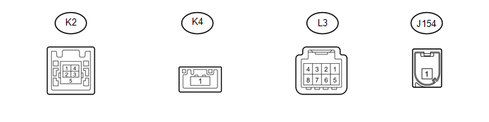
K3-1 (LV1)*3 | # |
LVDS communication signal |
- | - |
|
J151-1 | # |
- | - |
- |
| J151-3 |
# | - |
- | - |
|
J151-5 - J133-7 (GND1) |
# - BR | Power source of antenna |
Ignition switch ACC Radio switch on and AM or FM selected |
11 to 14 V |