DESCRIPTION This DTC is stored when the blind spot monitor sensor LH detects a short to +B in the outer rear view mirror indicator LH. |
DTC No. | DTC Detection Condition |
Trouble Area | | C1AB1 | Both of the following conditions are met:
- The blind spot monitor system is on
- The blind spot monitor sensor is not sending voltage to the indicator
but the indicator receives voltage above a specified level for a
specified period of time
|
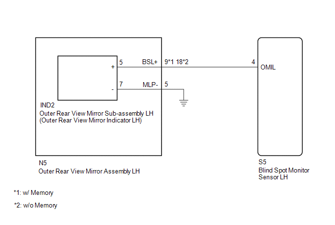
- Outer rear view mirror sub-assembly LH
- Outer rear view mirror assembly LH
- Harness or connector
- Blind spot monitor sensor LH
| WIRING DIAGRAM
 CAUTION / NOTICE / HINT
NOTICE: When checking for DTCs, make sure that the blind spot monitor system is turned on. PROCEDURE
(a) Clear the DTCs. Click here
 (b) Recheck for DTCs and check if the same DTC is output again.
Click here OK: No DTCs are output.
| OK |
 | USE SIMULATION METHOD TO CHECK |
|
NG |
 | |
| 2. |
CHECK HARNESS AND CONNECTOR (OUTER REAR VIEW MIRROR INDICATOR CIRCUIT) |
| (a) Disconnect the blind spot monitor sensor LH connector. |
 |
|
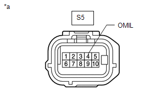
*a | Front view of wire harness connector
(to Blind Spot Monitor Sensor LH) | | |
(b) Measure the voltage according to the value(s) in the table below. Standard Voltage: |
Tester Connection | Switch Condition |
Specified Condition | |
S5-4 (OMIL) - Body ground |
Ignition switch ON | Below 1 V |
| OK |
| REPLACE BLIND SPOT MONITOR SENSOR LH |
|
NG | |
| |
| 3. |
CHECK HARNESS AND CONNECTOR (OUTER REAR VIEW MIRROR INDICATOR CIRCUIT) |
| (a) Disconnect the S5 blind spot monitor sensor LH connector. |
|
|
|
*a | Front view of wire harness connector
(to Blind Spot Monitor Sensor LH) | | |
(b) Disconnect the IND2 outer rear view mirror sub-assembly LH connector.
(c) Measure the voltage according to the value(s) in the table below. Standard Voltage: |
Tester Connection | Switch Condition |
Specified Condition | |
S5-4 (OMIL) - Body ground |
Ignition switch ON | Below 1 V |
| OK |
| REPLACE OUTER REAR VIEW MIRROR SUB-ASSEMBLY LH |
|
NG | |
| |
| 4. |
CHECK HARNESS AND CONNECTOR (OUTER REAR VIEW MIRROR INDICATOR CIRCUIT) |
| (a) Disconnect the S5 blind spot monitor sensor LH connector. |
|
|
|
*a | Front view of wire harness connector
(to Blind Spot Monitor Sensor LH) | | |
(b) Disconnect the N5 outer rear view monitor assembly LH connector. (c) Measure the voltage according to the value(s) in the table below.
Standard Voltage: |
Tester Connection | Switch Condition |
Specified Condition | |
S5-4 (OMIL) - Body ground |
Ignition switch ON | Below 1 V |
| OK |
| REPLACE OUTER REAR VIEW MIRROR ASSEMBLY LH |
| NG |
| REPAIR OR REPLACE HARNESS OR CONNECTOR | | 

