INSTALLATION CAUTION / NOTICE / HINT HINT: A bolt without a torque specification is shown in the standard bolt chart (See page
PROCEDURE 1. INSTALL CLEARANCE WARNING ECU ASSEMBLY
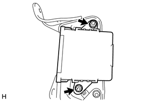
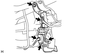
2. INSTALL CLEARANCE WARNING ECU WITH BRACKET
(b) Connect the ECU connectors and attach the harness clamp. NOTICE: Do not apply excessive force to the wire harnesses. 3. INSTALL LOWER INSTRUMENT PANEL FINISH PANEL SUB-ASSEMBLY RH 4. INSTALL NO.2 INSTRUMENT CLUSTER FINISH PANEL GARNISH 5. INSTALL INSTRUMENT SIDE PANEL RH 6. INSTALL NO.4 INSTRUMENT REGISTER SUB-ASSEMBLY 7. INSTALL LOWER NO. 2 INSTRUMENT PANEL AIRBAG ASSEMBLY 8. INSTALL LOWER INSTRUMENT PANEL 9. INSTALL NO. 2 INSTRUMENT PANEL UNDER COVER SUB-ASSEMBLY 10. CONNECT CABLE TO NEGATIVE BATTERY TERMINAL NOTICE: When disconnecting the cable, some systems need to be initialized after the cable is reconnected (See page
11. CHECK SRS WARNING LIGHT (a) Check the SRS warning light (See page |
Toyota Tundra Service Manual > Front Shock Absorber: Inspection
INSPECTION PROCEDURE 1. INSPECT FRONT SHOCK ABSORBER ASSEMBLY LH (a) Compress and extend the shock absorber rod 4 times or more. Check that there is no abnormal resistance or unusual sound during the operation. If there is any abnormality, replace the shock absorber assembly with a new one. NOTICE: ...

 ).
).