
DESCRIPTION The sonar ON/OFF indicator light and warning indicator lights are installed in the combination meter assembly. WIRING DIAGRAM 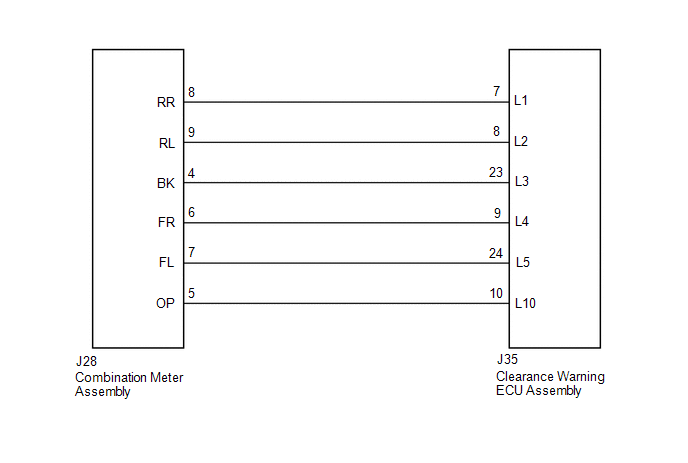 PROCEDURE
(a) Disconnect the J35 clearance warning ECU assembly connector. (b) Disconnect the J28 combination meter assembly connector. (c) Measure the resistance according to the value(s) in the table below. Standard Resistance:
(a) Replace the combination meter assembly with a normally functioning or new one (See page
(b) Check that the multi-information display in the combination meter assembly operates normally. OK: Multi-information display in the combination meter assembly operates normally.
|
Toyota Tundra Service Manual > Cruise Control System: Parts Location
PARTS LOCATION ILLUSTRATION *1 SKID CONTROL ECU (BRAKE ACTUATOR ASSEMBLY) *2 PARK/NEUTRAL POSITION SWITCH ASSEMBLY *3 THROTTLE BODY WITH MOTOR ASSEMBLY *4 ECM *5 FRONT SPEED SENSOR RH *6 FRONT SPEED SENSOR LH *7 REAR SPEED SENSOR RH *8 REAR SPEED SENSOR LH *9 ENGINE ROOM RELAY BLOCK ASSEMBLY, JUNCTI ...


