TERMINALS OF ECU 1. CHECK NAVIGATION RECEIVER ASSEMBLY 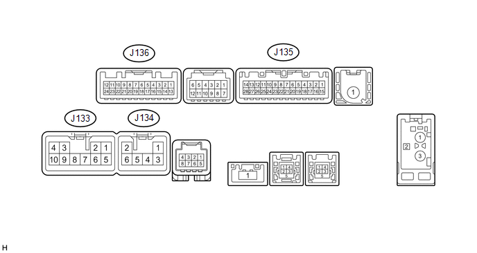 (a) Disconnect the J133 and J135 navigation receiver assembly connectors. (b) Measure the voltage and resistance according to the value(s) in the table below.
(c) Reconnect the J133 and J135 navigation receiver assembly connectors. (d) Measure the voltage and waveform according to the value(s) in the table below.
(e) Using an oscilloscope, check the waveform. 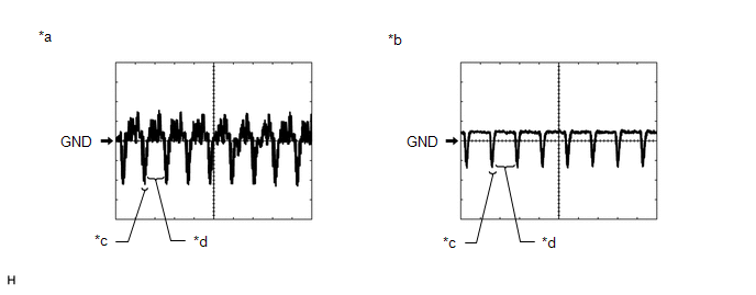
(1) Waveform 1 Measurement Condition
HINT: The video waveform changes according to the image sent by the television camera assembly. (2) Waveform 2 Measurement Condition
HINT: The video waveform changes according to the image sent by the television camera assembly. |
Toyota Tundra Service Manual > Outer Mirror Switch: Installation
INSTALLATION PROCEDURE 1. INSTALL OUTER MIRROR SWITCH ASSEMBLY (a) Attach the 2 claws to install the outer mirror switch assembly. 2. INSTALL LOWER INSTRUMENT PANEL FINISH PANEL SUB-ASSEMBLY LH 3. INSTALL INSTRUMENT SIDE PANEL LH 4. INSTALL COWL SIDE TRIM BOARD LH 5. INSTALL FRONT DOOR SCUFF PLATE L ...


