INSTALLATION PROCEDURE 1. INSTALL FRONT SKID CONTROL SENSOR CLAMP LH (a) Install the skid control sensor clamp (labeled A) with the bolt (labeled B). Torque: 13 N·m {127 kgf·cm, 9 ft·lbf} NOTICE: Install the bracket so that the rotation stopper (labeled C) touches the knuckle. 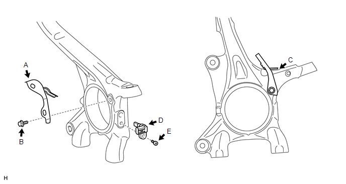 2. INSTALL FRONT SPEED SENSOR LH (a) Install the speed sensor (labeled D) with the hexagon socket head cap bolt (labeled E). Torque: 11 N·m {107 kgf·cm, 8 ft·lbf} NOTICE:
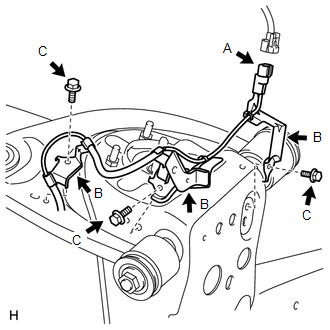
3. INSTALL FRONT SKID CONTROL SENSOR WIRE LH
(b) Install the 3 harness clamps (labeled B) with the 3 bolts (labeled C). Torque: 13 N·m {127 kgf·cm, 9 ft·lbf} NOTICE:
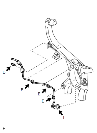
(d) Attach the 3 clips (labeled E). NOTICE:
(e) Connect the speed sensor connector (labeled F). NOTICE: Securely connect the connector. 4. INSTALL FRONT SKID CONTROL SENSOR CLAMP RH (a) Install the skid control sensor clamp (labeled A) with the bolt (labeled B). Torque: 13 N·m {127 kgf·cm, 9 ft·lbf} NOTICE: Install the bracket so that the rotation stopper (labeled C) touches the knuckle. 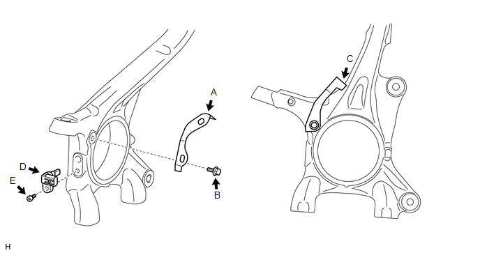 5. INSTALL FRONT SPEED SENSOR RH (a) Install the speed sensor (labeled D) with the hexagon socket head cap bolt (labeled E). Torque: 11 N·m {107 kgf·cm, 8 ft·lbf} NOTICE:
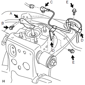
6. INSTALL FRONT SKID CONTROL SENSOR WIRE RH
(b) Install the connector (labeled C) with connect the connector (labeled C). (c) Install the 2 harness clamps (labeled D) with the 2 bolts (labeled E). Torque: for Bolt E : 13 N·m {127 kgf·cm, 9 ft·lbf} NOTICE:
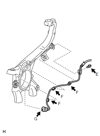
(e) Attach the 3 clips (labeled F). NOTICE:
(f) Connect the speed sensor connector (labeled G). NOTICE: Securely connect the connector. 7. INSTALL FRONT WHEEL Torque: for Aluminum Wheel : 131 N·m {1336 kgf·cm, 97 ft·lbf} for Steel Wheel : 209 N·m {2131 kgf·cm, 154 ft·lbf} 8. CONNECT CABLE TO NEGATIVE BATTERY TERMINAL 9. CHECK SPEED SENSOR SIGNAL (a) Check the speed sensor signal (See page
|
Toyota Tundra Service Manual > Headlight Leveling Switch: Inspection
INSPECTION PROCEDURE 1. INSPECT HEADLIGHT LEVELING SWITCH (a) Check the voltage. (1) Connect the battery positive (+) lead to terminal 1 (B) and the negative (-) lead to terminal 5 (E). (2) Measure the voltage according to the value(s) in the table below. Standard Voltage: Tester Connection Switch C ...