Components COMPONENTS ILLUSTRATION 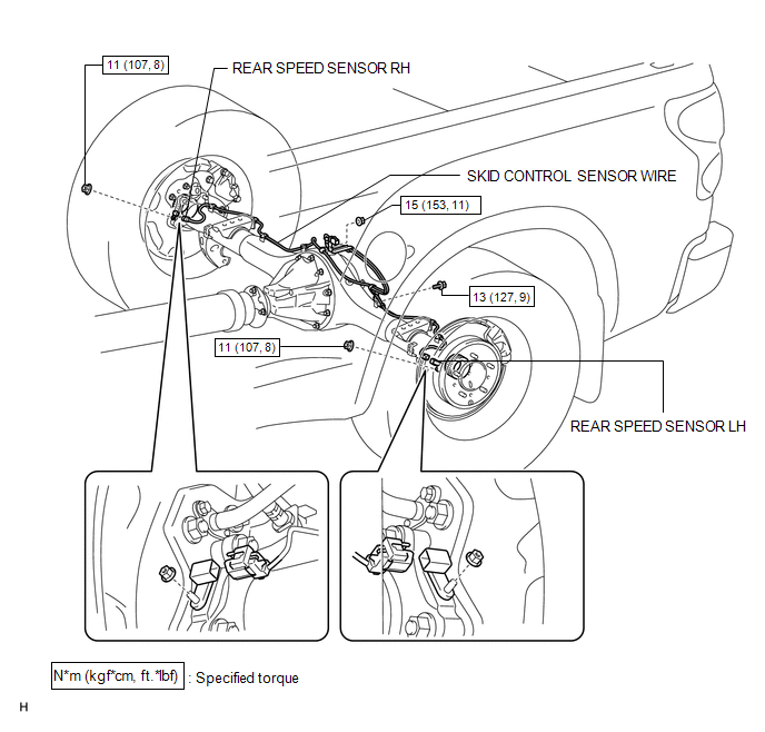 Installation INSTALLATION PROCEDURE 1. INSTALL SKID CONTROL SENSOR WIRE (a) Install the sensor clamp with the nut (labeled A). Torque: 15 N·m {153 kgf·cm, 11 ft·lbf} NOTICE: Make sure the clamp's rotation stopper touches the installation position. (b) Install the sensor clamp with the bolt (labeled B). Torque: 13 N·m {127 kgf·cm, 9 ft·lbf} NOTICE: When installing the clamp, do not twist the wire harness. (c) Attach the 7 clips (labeled C). NOTICE:
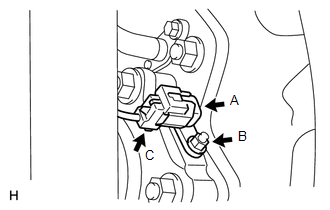
(d) Connect the sensor connector (labeled D). NOTICE: Securely connect the connector. 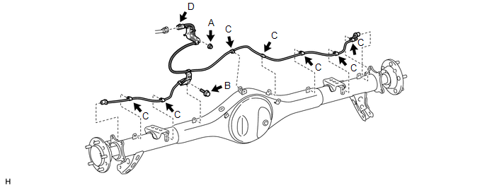 2. INSTALL REAR SPEED SENSOR LH
(b) Connect the speed sensor connector (labeled C). NOTICE: Securely connect the connector. 3. INSTALL REAR SPEED SENSOR RH
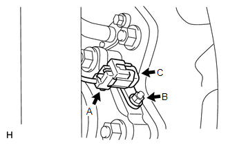
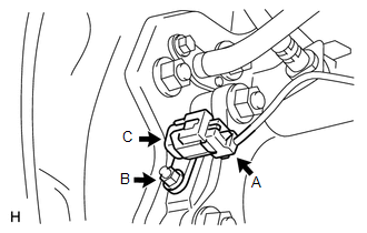
(b) Connect the speed sensor connector (labeled C). NOTICE: Securely connect the connector. 4. INSTALL REAR WHEEL Torque: for Aluminum Wheel : 131 N·m {1336 kgf·cm, 97 ft·lbf} for Steel Wheel : 209 N·m {2131 kgf·cm, 154 ft·lbf} 5. CONNECT CABLE TO NEGATIVE BATTERY TERMINAL 6. CHECK SPEED SENSOR SIGNAL (a) Check the speed sensor signal (See page
Removal REMOVAL PROCEDURE 1. PRECAUTION NOTICE: After
turning the ignition switch off, waiting time may be required before
disconnecting the cable from the battery terminal. Therefore, make sure
to read the disconnecting the cable from the battery terminal notice
before proceeding with work (See page 2. DISCONNECT CABLE FROM NEGATIVE BATTERY TERMINAL CAUTION: Wait at least 90 seconds after disconnecting the cable from the negative (-) battery terminal to disable the SRS system. 3. REMOVE REAR WHEEL 4. REMOVE REAR SPEED SENSOR LH
(b) Remove the nut (labeled B) and speed sensor (labeled C). 5. REMOVE REAR SPEED SENSOR RH
(b) Remove the nut (labeled B) and speed sensor (labeled C). 6. REMOVE SKID CONTROL SENSOR WIRE (a) Disconnect the sensor connector (labeled A). (b) Detach the 7 clips (labeled B). (c) Remove the bolt (labeled C). (d) Remove the nut (labeled D) and skid control sensor wire. 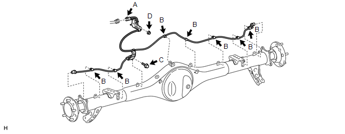 |
Toyota Tundra Service Manual > Rear Bumper (for Steel Type Bumper): Components
COMPONENTS ILLUSTRATION ILLUSTRATION ILLUSTRATION ILLUSTRATION ILLUSTRATION ILLUSTRATION ...