DESCRIPTION The trailer brake control ECU (brake control with bracket relay) is connected via the trailer socket and direct line.
The trailer brake control ECU (brake control with bracket relay) outputs a signal to the trailer socket. |
DTC No. | Detection Item |
INF Code | DTC Detection Condition |
Trouble Area | | C14A4 |
Output Circuit Temperature High / Over Current |
- | With
the ignition switch on and the IG terminal voltage from 11 to 14 V, the
trailer brake control ECU (brake control with bracket relay) output
circuit current value continuously exceeds 27.8 to 40 A for 1 second or
more |
- Harness or connector (Vehicle)
- Harness or connector (Trailer)
- Trailer brake control ECU (Brake control with bracket relay)
| | C14A6 |
Output Circuit Negative Voltage |
61 62 |
- INF Code: 61
- With the ignition switch on and the IG terminal voltage from 11 to 14 V,
an open circuit occurs in the trailer brake control ECU (brake control
with bracket relay) output circuit for 1.9 seconds or more
- INF Code: 62
- With the ignition switch on, the IG terminal voltage from 11 to 14 V and
the trailer brake control ECU (brake control with bracket relay) not
performing control, a voltage of 3.2 to 3.8 V or more is input to the
trailer brake control ECU (brake control with bracket relay) output
circuit
|
- Harness or connector (Vehicle)
- Harness or connector (Trailer)
- Trailer brake control ECU (Brake control with bracket relay)
| | C14AA |
ECU Malfunction(FET High Temperature) |
- | Any of the following is detected:
- With the ignition switch on and the IG terminal voltage from 11 to 14 V,
the trailer brake control ECU (brake control with bracket relay) output
circuit temperature continuously exceeds 160°C for 1 second or more
- With the ignition switch on and the IG terminal voltage from 11 to 14 V,
the trailer brake control ECU (brake control with bracket relay) output
circuit current value continuously exceeds 50 A for 1 second or more
- With the ignition switch on and the IG terminal voltage from 11 to 14 V,
the trailer brake control ECU (brake control with bracket relay) output
circuit current value continuously exceeds 100 A for 1 second or more
|
- Harness or connector (Vehicle)
- Harness or connector (Trailer)
- Trailer brake control ECU (Brake control with bracket relay)
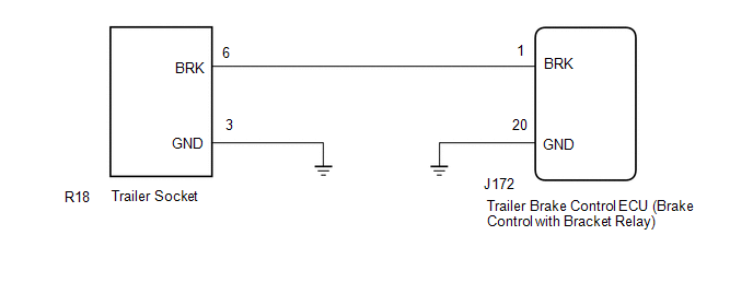
| WIRING DIAGRAM
 PROCEDURE
| 1. |
CHECK HARNESS AND CONNECTOR (BRAKE CONTROL WITH BRACKET RELAY - TRAILER SOCKET) |
(a) Turn the ignition switch off. (b) Disconnect the J172 trailer brake control ECU (brake control with bracket relay) connector.
(c) Inspect both the connector case and the terminal for deformation and corrosion.
OK: No deformation or corrosion. (d) Measure the resistance according to the value(s) in the table below.
Standard Resistance: |
Tester Connection | Condition |
Specified Condition | |
J172-1 (BRK) - R18-6 (BRK) |
Always | Below 1 Ω | |
J172-1 (BRK) - R18-6 (BRK) - Body ground |
Always | 10 kΩ or higher |
| NG |
 | REPAIR OR REPLACE HARNESS OR CONNECTOR (VEHICLE) |
|
OK |
 | |
| 2. |
CHECK TERMINAL VOLTAGE (BRK TERMINAL) |
| (a) Connect the J172 trailer brake control ECU (brake control with bracket relay) connector. |
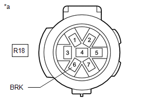 |
|
*a | Front view of wire harness connector
(to Trailer Brake Control ECU (Brake Control with Bracket Relay)) | | |
(b) Inspect both the connector case and the terminal for deformation and corrosion.
OK: No deformation or corrosion. (c) Turn the ignition switch to ON.
(d) Measure the voltage according to the value(s) in the table below. Standard Voltage: |
Tester Connection | Condition |
Specified Condition | |
R18-6 (BRK) - Body ground |
- Ignition switch ON
- No trailer brake control
| Below 3.5 V |
| NG |
| GO TO STEP 6 |
|
OK | |
| |
| 3. |
CHECK HARNESS AND CONNECTOR (GND TERMINAL) |
(a) Turn the ignition switch off. (b) Disconnect the J172 trailer brake control ECU (brake control with bracket relay) connector.
(c) Measure the resistance according to the value(s) in the table below.
Standard Resistance: |
Tester Connection | Condition |
Specified Condition | |
J172-20 (GND) - Body ground |
Always | Below 1 Ω |
| NG |
| REPAIR OR REPLACE HARNESS OR CONNECTOR (VEHICLE) |
|
OK | |
| |
| 4. |
CHECK HARNESS AND CONNECTOR (GND TERMINAL) |
| (a) Measure the resistance according to the value(s) in the table below.
Standard Resistance: |
Tester Connection | Condition |
Specified Condition | |
R18-3 (GND) - Body ground |
Always | Below 1 Ω | |
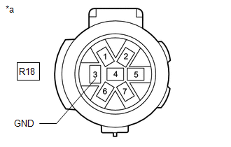 |
|
*a | Front view of wire harness connector
(to Trailer Brake Control ECU (Brake Control with Bracket Relay)) | | |
| NG |
| REPAIR OR REPLACE HARNESS OR CONNECTOR (VEHICLE) |
|
OK | |
| |
| 5. |
CHECK TERMINAL VOLTAGE (IG TERMINAL) | (a) Check the wire harness and connector of the connected trailer. Check items
- Connector link state
- Connector looseness or disconnection
- Deformation and corrosion of connector case and terminal
- Standard voltage and resistance of wire harness and connector (refer to manual of each trailer for standard values)
OK: No problem with check items.
| OK |
| REPLACE BRAKE CONTROL WITH BRACKET RELAY |
| NG |
| REPAIR OR REPLACE HARNESS OR CONNECTOR (TRAILER) |
| 6. |
CHECK TERMINAL VOLTAGE (BRK TERMINAL) |
(a) Turn the ignition switch off.
| (b) Disconnect the J172 trailer brake control ECU (brake control with bracket relay) connector. |
|
|
|
*a | Front view of wire harness connector
(to Trailer Brake Control ECU (Brake Control with Bracket Relay)) | | |
(c) Turn the ignition switch to ON. (d) Measure the voltage according to the value(s) in the table below.
Standard Voltage: |
Tester Connection | Condition |
Specified Condition | |
R18-6 (BRK) - Body ground |
Ignition switch ON | Below 3.5 V |
HINT: Before
replacing the trailer brake control ECU (brake control with bracket
relay), check that there are no malfunctions (GND short) in the trailer
side circuit. | OK |
| REPLACE BRAKE CONTROL WITH BRACKET RELAY |
| NG |
| REPAIR OR REPLACE HARNESS OR CONNECTOR (VEHICLE) | | 

