PARTS LOCATION ILLUSTRATION 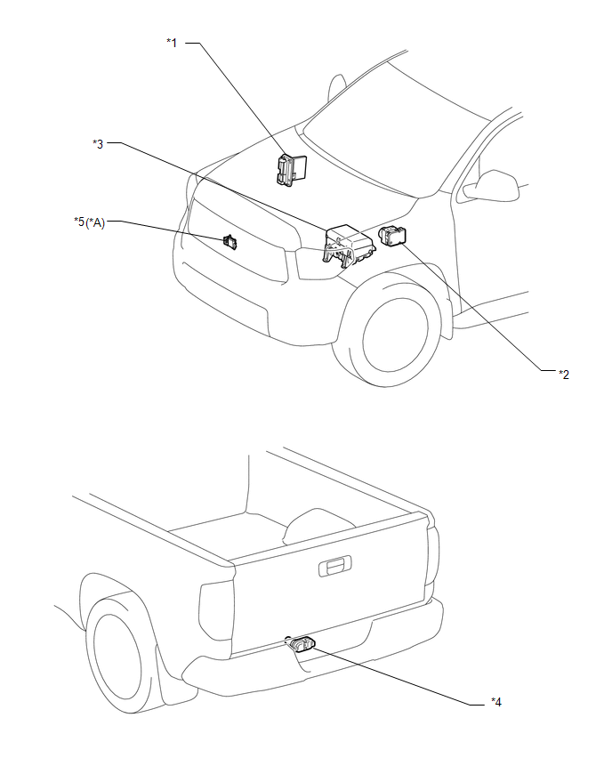
ILLUSTRATION 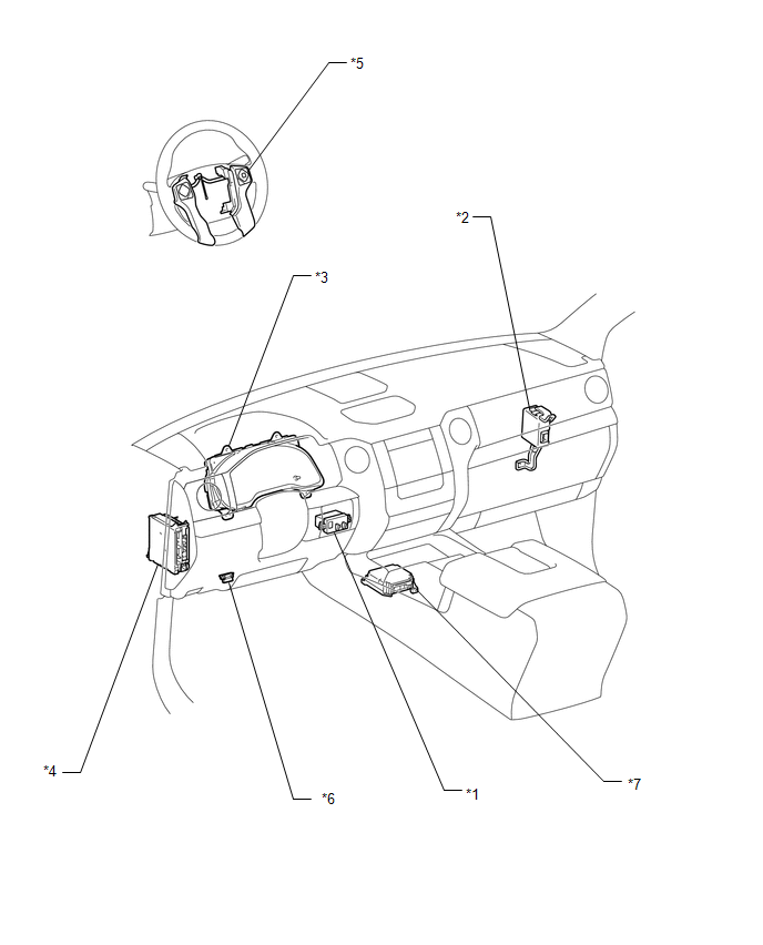
|
Toyota Tundra Service Manual > Audio / Video: Microphone Amplifier
ComponentsCOMPONENTS ILLUSTRATION *A for Double Cab - - *1 TELEPHONE MICROPHONE ASSEMBLY - - ILLUSTRATION *A for CrewMax *B w/o Sliding Roof *C w/ Sliding Roof - - *1 TELEPHONE MICROPHONE ASSEMBLY - - InstallationINSTALLATION PROCEDURE 1. INSTALL TELEPHONE MICROPHONE ASSEMBLY (a) Attach the 2 claws ...


