DESCRIPTION If a
malfunction is detected in the power supply circuit, the skid control
ECU (brake actuator assembly) stores this DTC and the fail-safe function
prohibits ABS operation. This DTC is stored when the +BS terminal
voltage meets one of the DTC detection conditions due to a malfunction
in the power supply or charging circuit such as the battery or
alternator circuit, etc. The DTC is cleared when the +BS terminal
voltage returns to normal. |
DTC No. | Detection Item |
DTC Detection Condition | Trouble Area | |
C1241 | Low Power Supply Voltage Malfunction |
Any of the following is detected:
- The +BS terminal voltage is less than 8.3 V and the skid control ECU
(brake actuator assembly) judge sthat power supply voltage is abnormal
for 0.56 seconds or more.
- When +BS terminal voltage is less than 8.3 V, power supply voltage of
vehicle speed sensor is continuously low for 0.21 seconds or more.
|
- ABS2 fuse
- Battery
- Charging system
- Power source circuit
- Ground circuit
- Internal power supply circuit of the skid control ECU (brake actuator assembly)
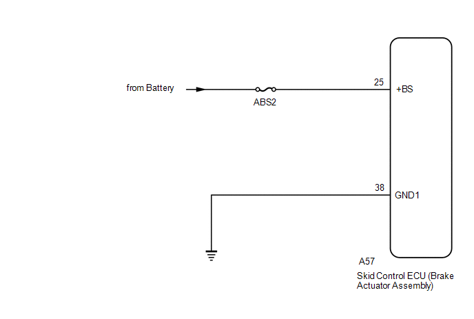
| WIRING DIAGRAM
 CAUTION / NOTICE / HINT
NOTICE:
- When replacing the skid control ECU (brake actuator assembly), perform
system variant learning and acceleration sensor zero point calibration.
Click here 
- Inspect the fuses for circuits related to this system before performing the following procedure.
PROCEDURE (a) Check the battery voltage.
Standard Voltage: |
Tester Connection | Condition |
Specified Condition | |
Positive (+) terminal - Negative (-) terminal |
Ignition switch off | 11 to 14 V |
| NG |
 | CHECK OR REPLACE CHARGING SYSTEM COMPONENT OR BATTERY |
|
OK |
 | |
| 2. |
CHECK HARNESS AND CONNECTOR (POWER SOURCE TERMINAL) |
| (a) Make sure that there is no looseness at the locking part and the connecting part of the connector.
OK: The connector is securely connected. |
 |
|
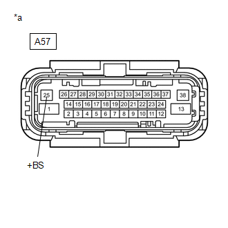
*a | Front view of wire harness connector
(to Skid Control ECU (Brake Actuator Assembly)) | | |
(b) Disconnect the A57 skid control ECU (brake actuator assembly) connector.
(c) Check both the connector case and the terminals for deformation and corrosion.
OK: No deformation or corrosion. (d) Measure the voltage according to the value(s) in the table below.
Standard Voltage: |
Tester Connection | Condition |
Specified Condition | |
A57-25 (+BS) - Body ground |
Always | 11 to 14 V |
| NG |
| REPAIR OR REPLACE HARNESS OR CONNECTOR (POWER SOURCE CIRCUIT) |
|
OK | |
| |
| 3. |
CHECK HARNESS AND CONNECTOR (GND1 TERMINAL) |
| (a) Turn the ignition switch off. |
 |
|
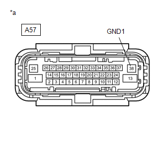
*a | Front view of wire harness connector
(to Skid Control ECU (Brake Actuator Assembly)) | | |
(b) Measure the resistance according to the value(s) in the table below.
Standard Resistance: |
Tester Connection | Condition |
Specified Condition | |
A57-38 (GND1) - Body ground |
Always | Below 1 Ω |
| NG |
| REPAIR OR REPLACE HARNESS OR CONNECTOR (GND1 CIRCUIT) |
|
OK | |
| |
(a) Reconnect the A57 skid control ECU (brake actuator assembly) connector.
(b) Clear the DTCs. Click here
(c) Turn the ignition switch off. (d) Start the engine. (e) Perform a road test.
(f) Check if the same DTC is output. Click here
|
Result | Proceed to | |
C1241 is not output | A | |
C1241 is output | B |
| A |
| USE SIMULATION METHOD TO CHECK |
| B |
| REPLACE BRAKE ACTUATOR ASSEMBLY | | 

