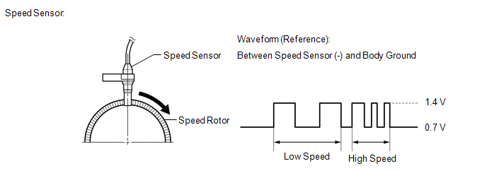
DESCRIPTION Each speed
sensor detects wheel speed and sends signals to the skid control ECU
(brake actuator assembly). These signals are used by the ABS control. HINT:
The
output voltage values shown below are for when the vehicle wire
harnesses are connected to the skid control ECU (brake actuator
assembly) and the speed sensors.
 |
DTC No. | Detection Item |
DTC Detection Condition | Trouble Area | |
C1330 | Open in Front Speed Sensor RH |
An open or short in the speed sensor signal circuit continues for 0.14 seconds or more. |
- Front speed sensor RH
- Skid control sensor wire
- Speed sensor circuit
- Front speed sensor installation
| | C1331 |
Open in Front Speed Sensor LH |
An open or short in the speed sensor signal circuit continues for 0.14 seconds or more. |
- Front speed sensor LH
- Skid control sensor wire
- Speed sensor circuit
- Front speed sensor installation
| | C1332 |
Open in Rear Speed Sensor RH |
An open or short in the speed sensor signal circuit continues for 0.14 seconds or more. |
- Rear speed sensor RH
- Skid control sensor wire
- Speed sensor circuit
- Rear speed sensor installation
| | C1333 |
Open in Rear Speed Sensor LH |
An open or short in the speed sensor signal circuit continues for 0.14 seconds or more. |
- Rear speed sensor LH
- Skid control sensor wire
- Speed sensor circuit
- Rear speed sensor installation
| | C1464 |
Front Speed Sensor RH | Any of the following is detected:
- After driving at a vehicle speed of 10 km/h or more, the vehicle speed
is 2 km/h or less and the maximum wheel speed is 10 km/h and the minimum
wheel speed is less than 2 km/h continuously for 180 seconds.
- After driving at 14 km/h or more and the non-driven wheel exceeds 14
km/h when the vehicle speed is less than 2 km/h (for 2WD Only)
- After driving at 14 km/h or more and the maximum wheel speed exceeds 14 km/h when the vehicle speed is less than 2 km/h
|
- Front speed sensor RH
- Speed sensor circuit
- Skid control sensor wire
- Front speed sensor rotor RH (front axle with ABS rotor bearing assembly RH)
- Front speed sensor installation
- Skid control ECU (brake actuator assembly)
| | C1465 |
Front Speed Sensor LH | Any of the following is detected:
- After driving at a vehicle speed of 10 km/h or more, the vehicle speed
is 2 km/h or less and the maximum wheel speed is 10 km/h and the minimum
wheel speed is less than 2 km/h continuously for 180 seconds.
- After driving at 14 km/h or more and the non-driven wheel exceeds 14
km/h when the vehicle speed is less than 2 km/h (for 2WD Only)
- After driving at 14 km/h or more and the maximum wheel speed exceeds 14 km/h when the vehicle speed is less than 2 km/h
|
- Front speed sensor LH
- Speed sensor circuit
- Skid control sensor wire
- Front speed sensor rotor LH (front axle with ABS rotor bearing assembly LH)
- Front speed sensor installation
- Skid control ECU (brake actuator assembly)
| | C1466 |
Rear Speed Sensor RH | Any of the following is detected:
- After driving at a vehicle speed of 10 km/h or more, the vehicle speed
is 2 km/h or less and the maximum wheel speed is 10 km/h and the minimum
wheel speed is less than 2 km/h continuously for 180 seconds.
- After driving at 14 km/h or more and the non-driven wheel exceeds 14
km/h when the vehicle speed is less than 2 km/h (for 2WD Only)
- After driving at 14 km/h or more and the maximum wheel speed exceeds 14 km/h when the vehicle speed is less than 2 km/h
|
- Rear speed sensor RH
- Speed sensor circuit
- Skid control sensor wire
- Rear speed sensor rotor RH (rear axle hub and bearing assembly RH)
- Rear speed sensor installation
- Skid control ECU (brake actuator assembly)
| | C1467 |
Rear Speed Sensor LH | Any of the following is detected:
- After driving at a vehicle speed of 10 km/h or more, the vehicle speed
is 2 km/h or less and the maximum wheel speed is 10 km/h and the minimum
wheel speed is less than 2 km/h continuously for 180 seconds.
- After driving at 14 km/h or more and the non-driven wheel exceeds 14
km/h when the vehicle speed is less than 2 km/h (for 2WD Only)
- After driving at 14 km/h or more and the maximum wheel speed exceeds 14 km/h when the vehicle speed is less than 2 km/h
|
- Rear speed sensor LH
- Speed sensor circuit
- Skid control sensor wire LH
- Rear speed sensor rotor LH (rear axle hub and bearing assembly LH)
- Rear speed sensor installation
- Skid control ECU (brake actuator assembly)
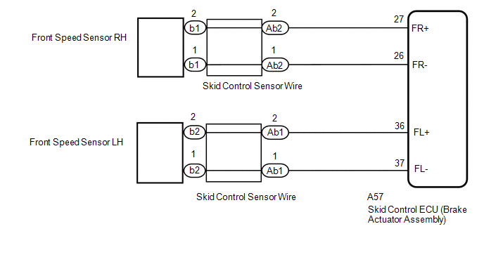
| WIRING DIAGRAM for Front
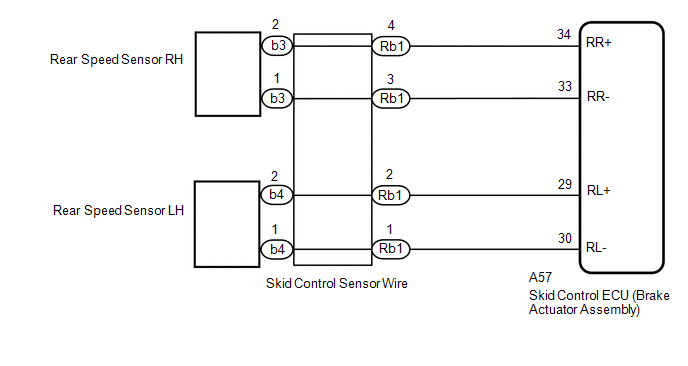
 for Rear for Rear
 CAUTION / NOTICE / HINT
NOTICE: When
replacing the skid control ECU (brake actuator assembly), perform
system variant learning and acceleration sensor zero point calibration. Click here
 PROCEDURE
(a) Check that the DTC is output.
Click here
|
Result | Proceed to | |
C1330, C1331, C1464 or C1465 is output |
A | | C1332, C1333, C1466 or C1467 is output |
B |
| B |
 | GO TO STEP 11 |
|
A |
 | |
| 2. |
CHECK FRONT SPEED SENSOR INSTALLATION |
| (a) Turn the ignition switch off. |
 |
|
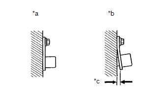
*a | Normal | |
*b | Abnormal | |
*c | Clearance | | |
(b) Check the speed sensor installation. Click here
OK: There is no clearance between the sensor and the front steering knuckle.
The installation bolt is tightened properly.
| NG |
| REINSTALL OR REPLACE FRONT SPEED SENSOR |
|
OK | |
| |
| 3. |
CHECK FRONT SPEED SENSOR (CHECK FOR FOREIGN MATTER) |
(a) Remove the front speed sensor. Click here
(b) Check the front speed sensor tip.
OK: The sensor tip is free of scratches, oil, and foreign matter.
NOTICE:
- If there is oil or foreign matter on the speed sensor, clean the speed sensor.
- If the speed sensor is damaged, replace the speed sensor with a new one.
- Check the speed sensor signal after cleaning or replacement.
Click here
| NG |
| CLEAN OR REPLACE FRONT SPEED SENSOR |
|
OK | |
| |
| 4. |
INSPECT BRAKE ACTUATOR ASSEMBLY (POWER SOURCE CIRCUIT) |
| (a) Make sure that there is no looseness at the locking part and the connecting part of the connectors.
OK: The connector is securely connected. |
 |
|
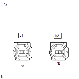
*A | for RH | |
*B | for LH | |
*a | Front view of wire harness connector
(to Front Speed Sensor) | | |
(b) Disconnect the b1 or b2 front speed sensor connector. (c) Check both the connector case and the terminals for deformation and corrosion.
OK: No deformation or corrosion. (d) Turn the ignition switch to ON.
(e) Measure the voltage according to the value(s) in the table below. Standard Voltage: for RH |
Tester Connection | Condition |
Specified Condition | |
b1-2 - Body ground | Ignition switch ON |
5.5 to 14 V | for LH |
Tester Connection | Condition |
Specified Condition | |
b2-2 - Body ground | Ignition switch ON |
5.5 to 14 V |
| NG |
| GO TO STEP 9 |
|
OK | |
| |
| 5. |
INSPECT BRAKE ACTUATOR ASSEMBLY (GROUND CIRCUIT) |
| (a) Measure the voltage according to the value(s) in the table below.
Standard Voltage: for RH |
Tester Connection | Condition |
Specified Condition | |
b1-2 - b1-1 | Ignition switch ON |
5.5 to 14 V | for LH |
Tester Connection | Condition |
Specified Condition | |
b2-2 - b2-1 | Ignition switch ON |
5.5 to 14 V | |
 |
|
*A | for RH | |
*B | for LH | |
*a | Front view of wire harness connector
(to Front Speed Sensor) | | |
| NG |
| GO TO STEP 7 |
|
OK | |
| |
| 6. |
CHECK FRONT SPEED SENSOR ROTOR (CHECK FOR FOREIGN MATTER) |
(a) Remove the front speed sensor rotor (front axle with ABS rotor bearing assembly).
Click here Click here (b) Check the speed sensor rotor.
OK: The rotor is free of scratches, oil, and foreign matter. NOTICE:
Check the speed sensor signal after cleaning or replacement. Click here
HINT:
- The front speed sensor rotor is incorporated into the front axle hub sub-assembly.
- If the front speed sensor rotor needs to be replaced, replace it together with the front axle with ABS rotor bearing assembly.
|
Result | Proceed to | |
OK | A | |
NG (The speed sensor rotor is damaged) |
B | | NG (There is oil or foreign matter on the speed sensor rotor) |
C |
| A |
| REPLACE FRONT SPEED SENSOR |
| B |
| REPLACE FRONT AXLE WITH ABS ROTOR BEARING ASSEMBLY |
| C |
| CLEAN FRONT SPEED SENSOR ROTOR |
| 7. |
INSPECT SKID CONTROL SENSOR WIRE | (a) Turn the ignition switch off.

|
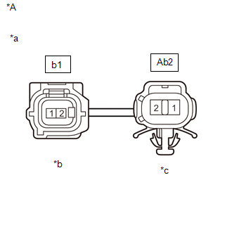
*A | for RH | |
*a | Front view of skid control sensor wire | |
*b | Front view of wire harness connector
(to Sensor Side Connector) | |
*c | Front view of wire harness connector
(to Vehicle Side Connector) |

|
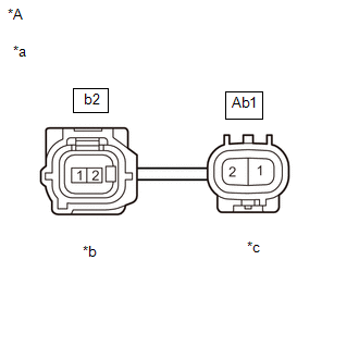
*A | for LH | |
*a | Front view of skid control sensor wire | |
*b | Front view of wire harness connector
(to Sensor Side Connector) | |
*c | Front view of wire harness connector
(to Vehicle Side Connector) | (b) Make sure that there is no looseness at the locking part and the connecting part of the connectors.
OK: The connector is securely connected. (c) Disconnect the b1 or Ab2 skid control sensor wire.
(d) Check both the connector case and the terminals for deformation and corrosion.
OK: No deformation or corrosion. (e) Measure the resistance according to the value(s) in the table below.
Standard Resistance: for RH |
Tester Connection | Condition |
Specified Condition | |
b1-1 - Ab2-1 | Always |
Below 1 Ω | |
b1-1 - Ab2-2 | Always |
10 kΩ or higher | |
b1-1 or Ab2-1 - Body ground |
Always | 10 kΩ or higher | for LH |
Tester Connection | Condition |
Specified Condition | |
b2-1 - Ab1-1 | Always |
Below 1 Ω | |
b2-1 - Ab1-2 | Always |
10 kΩ or higher | |
b2-1 or Ab1-1 - Body ground |
Always | 10 kΩ or higher |
NOTICE: Check the speed sensor signal after replacement. Click here
| NG | |
REPLACE SKID CONTROL SENSOR WIRE |
|
OK | |
| |
| 8. |
CHECK HARNESS AND CONNECTOR (BRAKE ACTUATOR ASSEMBLY - SKID CONTROL SENSOR WIRE) |
(a) Turn the ignition switch off. (b) Make sure that there is no looseness at the locking part and the connecting part of the connectors.
OK: The connector is securely connected. (c) Disconnect the A57 skid control ECU (brake actuator assembly) connector.
(d) Check both the connector case and the terminals for deformation and corrosion.
OK: No deformation or corrosion. (e) Measure the resistance according to the value(s) in the table below.
Standard Resistance: for RH: |
Tester Connection | Condition |
Specified Condition | |
A57-26 (FR-) - Ab2-1 |
Always | Below 1 Ω | |
A57-26 (FR-) or Ab2-1 - Body ground |
Always | 10 kΩ or higher | for LH: |
Tester Connection | Condition |
Specified Condition | |
A57-37 (FL-) - Ab1-1 |
Always | Below 1 Ω | |
A57-37 (FL-) or Ab1-1 - Body ground |
Always | 10 kΩ or higher |
| OK |
| REPLACE BRAKE ACTUATOR ASSEMBLY |
| NG |
| REPAIR OR REPLACE HARNESS OR CONNECTOR |
| 9. |
INSPECT SKID CONTROL SENSOR WIRE | (a) Turn the ignition switch off.
|
*A | for RH | |
*a | Front view of skid control sensor wire | |
*b | Front view of wire harness connector
(to Sensor Side Connector) | |
*c | Front view of wire harness connector
(to Vehicle Side Connector) |
|
*A | for LH | |
*a | Front view of skid control sensor wire | |
*b | Front view of wire harness connector
(to Sensor Side Connector) | |
*c | Front view of wire harness connector
(to Vehicle Side Connector) | (b) Make sure that there is no looseness at the locking part and the connecting part of the connectors.
OK: The connector is securely connected. (c) Disconnect the Ab2 or Ab1 skid control sensor wire.
(d) Check both the connector case and the terminals for deformation and corrosion.
OK: No deformation or corrosion. (e) Measure the resistance according to the value(s) in the table below.
Standard Resistance: for RH |
Tester Connection | Condition |
Specified Condition | |
b1-2 - Ab2-2 | Always |
Below 1 Ω | |
b1-2 - Ab2-1 | Always |
10 kΩ or higher | |
b1-2 or Ab2-2 - Body ground |
Always | 10 kΩ or higher | for LH |
Tester Connection | Condition |
Specified Condition | |
b2-2 - Ab1-2 | Always |
Below 1 Ω | |
b2-2 - Ab1-1 | Always |
10 kΩ or higher | |
b2-2 or Ab1-2 - Body ground |
Always | 10 kΩ or higher |
NOTICE: Check the speed sensor signal after replacement. Click here
| NG | |
REPLACE SKID CONTROL SENSOR WIRE |
|
OK | |
| |
| 10. |
CHECK HARNESS AND CONNECTOR (BRAKE ACTUATOR ASSEMBLY - SKID CONTROL SENSOR WIRE) |
(a) Turn the ignition switch off. (b) Make sure that there is no looseness at the locking part and the connecting part of the connectors.
OK: The connector is securely connected. (c) Disconnect the A57 skid control ECU (brake actuator assembly) connector.
(d) Check both the connector case and the terminals for deformation and corrosion.
OK: No deformation or corrosion. (e) Measure the resistance according to the value(s) in the table below.
Standard Resistance: for RH: |
Tester Connection | Condition |
Specified Condition | |
A57-27 (FR+) - Ab2-2 |
Always | Below 1 Ω | |
A57-27 (FR+) or Ab2-2 - Body ground |
Always | 10 kΩ or higher | for LH: |
Tester Connection | Condition |
Specified Condition | |
A57-36 (FL+) - Ab2-2 |
Always | Below 1 Ω | |
A57-36 (FL+) or Ab2-2 - Body ground |
Always | 10 kΩ or higher |
| OK |
| REPLACE BRAKE ACTUATOR ASSEMBLY |
| NG |
| REPAIR OR REPLACE HARNESS OR CONNECTOR |
| 11. |
CHECK REAR SPEED SENSOR INSTALLATION |
| (a) Turn the ignition switch off. | |
|
|
*a | Normal | |
*b | Abnormal | |
*c | Clearance | | |
(b) Check the speed sensor installation. Click here
OK: There is no clearance between the sensor and the rear axle carrier.
The installation bolt is tightened properly.
| NG |
| REINSTALL OR REPLACE REAR SPEED SENSOR |
|
OK | |
| |
| 12. |
CHECK REAR SPEED SENSOR (CHECK FOR FOREIGN MATTER) |
(a) Remove the rear speed sensor. Click here
(b) Check the front speed sensor tip.
OK: The sensor tip is free of scratches, oil, and foreign matter.
NOTICE:
- If there is oil or foreign matter on the speed sensor, clean the speed sensor.
- If the speed sensor is damaged, replace the speed sensor with a new one.
- Check the speed sensor signal after cleaning or replacement.
Click here
| NG |
| CLEAN OR REPLACE REAR SPEED SENSOR |
|
OK | |
| |
| 13. |
INSPECT BRAKE ACTUATOR ASSEMBLY (POWER SOURCE CIRCUIT) |
| (a) Make sure that there is no looseness at the locking part and the connecting part of the connectors.
OK: The connector is securely connected. |
 |
|
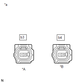
*A | for RH | |
*B | for LH | |
*a | Front view of wire harness connector
(to Rear Speed Sensor) | | |
(b) Disconnect the b3 or b4 rear speed sensor connector. (c) Check both the connector case and the terminals for deformation and corrosion.
OK: No deformation or corrosion. (d) Turn the ignition switch to ON.
(e) Measure the voltage according to the value(s) in the table below. Standard Voltage: for RH |
Tester Connection | Condition |
Specified Condition | |
b3-2 - Body ground | Ignition switch ON |
5.5 to 14 V | for LH |
Tester Connection | Condition |
Specified Condition | |
b3-2 - Body ground | Ignition switch ON |
5.5 to 14 V |
| NG |
| GO TO STEP 18 |
|
OK | |
| |
| 14. |
INSPECT BRAKE ACTUATOR ASSEMBLY (GROUND CIRCUIT) |
| (a) Measure the voltage according to the value(s) in the table below.
Standard Voltage: for RH |
Tester Connection | Condition |
Specified Condition | |
b3-2 - b3-1 | Ignition switch ON |
5.5 to 14 V | for LH |
Tester Connection | Condition |
Specified Condition | |
b4-2 - b4-1 | Ignition switch ON |
5.5 to 14 V | | |
|
|
*A | for RH | |
*B | for LH | |
*a | Front view of wire harness connector
(to Rear Speed Sensor) | | |
| NG |
| GO TO STEP 16 |
|
OK | |
| |
| 15. |
CHECK REAR SPEED SENSOR ROTOR (CHECK FOR FOREIGN MATTER) |
(a) Remove the rear speed sensor rotor (rear axle hub and bearing assembly).
Click here (b) Check the speed sensor rotor.
OK: The rotor is free of scratches, oil, and foreign matter. NOTICE:
Check the speed sensor signal after cleaning or replacement. Click here
HINT:
- The front speed sensor rotor is incorporated into the front axle hub sub-assembly.
- If the front speed sensor rotor needs to be replaced, replace it together with the rear axle hub and bearing assembly.
|
Result | Proceed to | |
OK | A | |
NG (The speed sensor rotor is damaged) |
B | | NG (There is foreign matter on the speed sensor rotor) |
C |
| A |
| REPLACE REAR SPEED SENSOR |
| B |
| REPLACE REAR AXLE HUB AND BEARING ASSEMBLY |
| C |
| CLEAN FRONT SPEED SENSOR ROTOR |
| 16. |
INSPECT SKID CONTROL SENSOR WIRE | (a) Turn the ignition switch off.

|
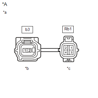
*A | for RH | |
*a | Front view of skid control sensor wire | |
*b | Front view of wire harness connector
(to Sensor Side Connector) | |
*c | Front view of wire harness connector
(to Vehicle Side Connector) |
|
*A | for LH | |
*a | Front view of skid control sensor wire | |
*b | Front view of wire harness connector
(to Sensor Side Connector) | |
*c | Front view of wire harness connector
(to Vehicle Side Connector) | (b) Make sure that there is no looseness at the locking part and the connecting part of the connectors.
OK: The connector is securely connected. (c) Disconnect the Rb1 skid control sensor wire.
(d) Check both the connector case and the terminals for deformation and corrosion.
OK: No deformation or corrosion. (e) Measure the resistance according to the value(s) in the table below.
Standard Resistance: for RH |
Tester Connection | Condition |
Specified Condition | |
b3-1 - Rb1-3 | Always |
Below 1 Ω | |
b3-1 - Rb1-4 | Always |
10 kΩ or higher | |
b3-1 - Rb1-1 | Always |
10 kΩ or higher | |
b3-1 - Rb1-2 | Always |
10 kΩ or higher | |
b3-1 or Rb1-3 - Body ground |
Always | 10 kΩ or higher | for LH |
Tester Connection | Condition |
Specified Condition | |
b4-1 - Rb1-1 | Always |
Below 1 Ω | |
b4-1 - Rb1-2 | Always |
10 kΩ or higher | |
b4-1 - Rb1-3 | Always |
10 kΩ or higher | |
b4-1 - Rb1-4 | Always |
10 kΩ or higher | |
b4-1 or Rb1-1 - Body ground |
Always | 10 kΩ or higher |
NOTICE: Check the speed sensor signal after replacement. Click here
| NG | |
REPLACE SKID CONTROL SENSOR WIRE |
|
OK | |
| |
| 17. |
CHECK HARNESS AND CONNECTOR (BRAKE ACTUATOR ASSEMBLY - SKID CONTROL SENSOR WIRE) |
(a) Turn the ignition switch off. (b) Make sure that there is no looseness at the locking part and the connecting part of the connectors.
OK: The connector is securely connected. (c) Disconnect the A57 skid control ECU (brake actuator assembly) connector.
(d) Check both the connector case and the terminals for deformation and corrosion.
OK: No deformation or corrosion. (e) Measure the resistance according to the value(s) in the table below.
Standard Resistance: for RH: |
Tester Connection | Condition |
Specified Condition | |
A57-33 (RR-) - Rb1-3 |
Always | Below 1 Ω | |
A57-33 (RR-) or Rb1-3 - Body ground |
Always | 10 kΩ or higher | for LH: |
Tester Connection | Condition |
Specified Condition | |
A57-30 (RL-) - Rb1-1 |
Always | Below 1 Ω | |
A57-30 (RL-) or Rb1-1 - Body ground |
Always | 10 kΩ or higher |
| OK |
| REPLACE BRAKE ACTUATOR ASSEMBLY |
| NG |
| REPAIR OR REPLACE HARNESS OR CONNECTOR |
| 18. |
INSPECT SKID CONTROL SENSOR WIRE | (a) Turn the ignition switch off.
|
*A | for RH | |
*a | Front view of skid control sensor wire | |
*b | Front view of wire harness connector
(to Sensor Side Connector) | |
*c | Front view of wire harness connector
(to Vehicle Side Connector) |

|
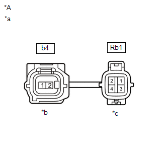
*A | for LH | |
*a | Front view of skid control sensor wire | |
*b | Front view of wire harness connector
(to Sensor Side Connector) | |
*c | Front view of wire harness connector
(to Vehicle Side Connector) | (b) Make sure that there is no looseness at the locking part and the connecting part of the connectors.
OK: The connector is securely connected. (c) Disconnect the Rb1 skid control sensor wire.
(d) Check both the connector case and the terminals for deformation and corrosion.
OK: No deformation or corrosion. (e) Measure the resistance according to the value(s) in the table below.
Standard Resistance: for RH |
Tester Connection | Condition |
Specified Condition | |
b3-2 - Rb1-4 | Always |
Below 1 Ω | |
b3-2 - Rb1-3 | Always |
10 kΩ or higher | |
b3-2 - Rb1-1 | Always |
10 kΩ or higher | |
b3-2 - Rb1-2 | Always |
10 kΩ or higher | |
b3-2 or Rb1-4 - Body ground |
Always | 10 kΩ or higher | for LH |
Tester Connection | Condition |
Specified Condition | |
b4-2 - Rb1-2 | Always |
Below 1 Ω | |
b4-2 - Rb1-1 | Always |
10 kΩ or higher | |
b4-2 - Rb1-3 | Always |
10 kΩ or higher | |
b4-2 - Rb1-4 | Always |
10 kΩ or higher | |
b4-2 or Rb1-2 - Body ground |
Always | 10 kΩ or higher |
NOTICE: Check the speed sensor signal after replacement. Click here
| NG | |
REPLACE SKID CONTROL SENSOR WIRE |
|
OK | |
| |
| 19. |
CHECK HARNESS AND CONNECTOR (BRAKE ACTUATOR ASSEMBLY - SKID CONTROL SENSOR WIRE) |
(a) Turn the ignition switch off. (b) Make sure that there is no looseness at the locking part and the connecting part of the connectors.
OK: The connector is securely connected. (c) Disconnect the A57 skid control ECU (brake actuator assembly) connector.
(d) Check both the connector case and the terminals for deformation and corrosion.
OK: No deformation or corrosion. (e) Measure the resistance according to the value(s) in the table below.
Standard Resistance: for RH: |
Tester Connection | Condition |
Specified Condition | |
A57-34 (RR+) - Rb1-4 |
Always | Below 1 Ω | |
A57-34 (RR+) or Rb1-4 - Body ground |
Always | 10 kΩ or higher | for LH: |
Tester Connection | Condition |
Specified Condition | |
A57-29 (RL+) - Rb1-2 |
Always | Below 1 Ω | |
A57-29 (RL+) or Rb1-2 - Body ground |
Always | 10 kΩ or higher |
| OK |
| REPLACE BRAKE ACTUATOR ASSEMBLY |
| NG |
| REPAIR OR REPLACE HARNESS OR CONNECTOR | | 

