DESCRIPTION If a malfunction is detected in the power supply circuit, the skid control ECU (brake actuator assembly) stores this DTC and the fail-safe function prohibits ABS operation. This DTC is stored when the +BS terminal voltage deviates due to a malfunction in a power supply or charging system circuit such as the battery or alternator circuit, etc.
WIRING DIAGRAM Refer to DTC C1241. Click here CAUTION / NOTICE / HINT NOTICE:
PROCEDURE
(a) Check the battery voltage. Standard Voltage:
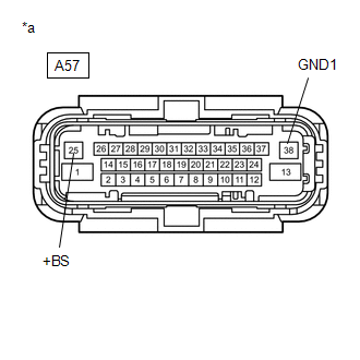
(b) Disconnect the A57 skid control ECU (brake actuator assembly) connector. (c) Check both the connector case and the terminals for deformation and corrosion. OK: No deformation or corrosion. (d) Measure the voltage according to the value(s) in the table below. Standard Voltage:
(a) Turn the ignition switch off. (b) Reconnect the A57 skid control ECU (brake actuator assembly) connector. (c) Clear the DTCs. Click here (d) Turn the ignition switch off. (e) Start the engine. (f) Perform a road test. (g) Check if the same DTC is output. Click here
|
Toyota Tundra Service Manual > Vehicle Stability Control System: Diagnostic Trouble Code Chart
DIAGNOSTIC TROUBLE CODE CHART Vehicle Stability Control System DTC No. Detection Item Link C1201 Engine Control System Malfunction C1225 SM Solenoid Circuit C1226 SA2 Solenoid Circuit C1227 SA3 Solenoid Circuit C1228 STR Solenoid Circuit C1234 Yaw Rate Sensor C1237 Speed Sensor Rotor Faulty C1241 Lo ...