DESCRIPTION This DTC is
stored when the skid control ECU (brake actuator assembly) judges that
an abnormality occurred in the circuit used to operate the pump motor. |
DTC No. | Detection Item |
DTC Detection Condition | Trouble Area | |
C1428 | Motor Circuit Malfunction |
Any of the following is detected:
- When the pump motor is not operating and the pump motor voltage is continuously 0.93 V or higher for 10 seconds.
- When a malfunction occurs in the pump motor circuit.
- When the switching voltage of the pump motor decreases while the pump motor is operating.
- When a malfunction occurs in the input voltage of the pump motor after the pump motor is operated.
| Pump motor circuit | WIRING DIAGRAM
Refer to DTC C146C. Click here  CAUTION / NOTICE / HINT
NOTICE:
- When replacing the skid control ECU (brake actuator assembly), perform
system variant learning and acceleration sensor zero point calibration.
Click here
- Inspect the fuses for circuits related to this system before performing the following procedure.
PROCEDURE |
1. | CHECK HARNESS AND CONNECTOR (+BM TERMINAL) |
| (a) Make sure that there is no looseness at the locking part and the connecting part of the connector.
OK: The connector is securely connected. |
 |
|
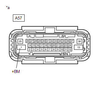
*a | Front view of wire harness connector
(to Skid Control ECU (Brake Actuator Assembly)) | | |
(b) Disconnect the A57 skid control ECU (brake actuator assembly) connector.
(c) Check both the connector case and the terminals for deformation and corrosion.
OK: No deformation or corrosion. (d) Measure the voltage according to the value(s) in the table below.
Standard Voltage: |
Tester Connection | Condition |
Specified Condition | |
A57-1 (+BM) - Body ground |
Always | 11 to 14 V |
| NG |
 | REPAIR OR REPLACE HARNESS OR CONNECTOR (+BM CIRCUIT) |
|
OK |
 | |
| 2. |
CHECK HARNESS AND CONNECTOR (GND2 TERMINAL) |
| (a) Measure the resistance according to the value(s) in the table below.
Standard Resistance: |
Tester Connection | Condition |
Specified Condition | |
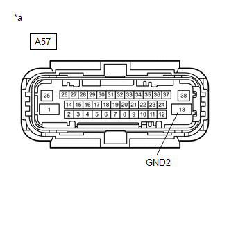
A57-13 (GND2) - Body ground |
Always | Below 1 Ω | |
 |
|
*a | Front view of wire harness connector
(to Skid Control ECU (Brake Actuator Assembly)) | | |
| NG |
| REPAIR OR REPLACE HARNESS OR CONNECTOR (GND2 CIRCUIT) |
|
OK | |
| |
(a) Reconnect the A57 skid control ECU (brake actuator assembly) connector.
(b) Clear the DTCs. Click here
(c) Turn the ignition switch off. (d) Start the engine. (e) Perform a road test.
(f) Check if the same DTC is output. Click here
|
Result | Proceed to | |
C1428 is not output | A | |
C1428 is output | B |
| A |
| USE SIMULATION METHOD TO CHECK |
| B |
| REPLACE BRAKE ACTUATOR ASSEMBLY | | 

