DESCRIPTION The skid control ECU (brake actuator assembly) receives signals from the steering angle sensor (spiral with sensor cable sub-assembly) via CAN communication. HINT: If there is a malfunction in the bus lines between the steering angle sensor (spiral with sensor cable sub-assembly) and the CAN communication system, DTC U0126 (Lost Communication with Steering Angle Sensor Module) is output. When U0126 is output together with C1434, inspect and repair the trouble areas indicated by U0126 first. DTCs may be stored if one of the following occurs:
WIRING DIAGRAM Refer to DTC C1432. Click here CAUTION / NOTICE / HINT NOTICE: Inspect the fuses for circuits related to this system before performing the following procedure. HINT: When a speed sensor or the yaw rate and acceleration sensor (airbag sensor assembly) is malfunctioning, DTCs for the steering angle sensor (spiral with sensor cable sub-assembly) may be stored even though the steering angle sensor (spiral with sensor cable sub-assembly) is normal. When DTCs for a speed sensor or yaw rate and acceleration sensor (airbag sensor assembly) are output together with DTCs for the steering angle sensor (spiral with sensor cable sub-assembly), inspect and repair the speed sensor or yaw rate and acceleration sensor (airbag sensor assembly) first, and then inspect and repair the steering angle sensor (spiral with sensor cable sub-assembly). PROCEDURE
(a) Check that no CAN communication system and speed sensor or yaw rate and acceleration sensor (airbag sensor assembly) DTCs are output. Click here
HINT:
(a) Turn the ignition switch off. (b) Check that the steering angle sensor (spiral with sensor cable sub-assembly) has been installed properly. Click here OK: The steering angle sensor (spiral with sensor cable sub-assembly) installation is normal.
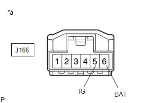
(b) Make sure that there is no looseness at the locking part and the connecting part of the connector. OK: The connector is securely connected. (c) Disconnect the J166 steering angle sensor (spiral with sensor cable sub-assembly) connector. (d) Check both the connector case and the terminals for deformation and corrosion. OK: No deformation or corrosion. (e) Measure the voltage according to the value(s) in the table below. Standard Voltage:
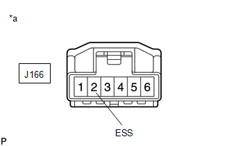
(b) Measure the resistance according to the value(s) in the table below. NOTICE: Before measuring the resistance of the steering angle sensor (spiral with sensor cable sub-assembly), turn the ignition switch off and leave the vehicle for 1 minute or more without operating the key or switches, or opening or closing the doors. Standard Resistance:
|
Toyota Tundra Service Manual > Touch Select 2-4 And High-low System: Transfer Shift Motor Control Circuit Circuit Open (P17A8,P17A9)
DESCRIPTION This DTC is detected when an open circuit or short to ground is detected in the transfer shift motor drive circuit. DTC Code DTC Detection Condition Diagnosis Condition Malfunction Status Malfunction Time Other Trouble Area P17A8 Ignition switch ON (when transfer shift motor is not opera ...