REMOVAL PROCEDURE 1. REMOVE PRECAUTION NOTICE: After
turning the ignition switch off, waiting time be required before
disconnecting the cable from the battery terminal. Therefore, make sure
to read the disconnecting the cable from the battery terminal notice
before proceeding with work (See page 2. DISCONNECT CABLE FROM NEGATIVE BATTERY TERMINAL CAUTION: Wait at least 90 seconds after disconnecting the cable from the negative (-) battery terminal to disable the SRS system. NOTICE: When disconnecting the cable some systems need to be initialized after the cable is reconnected. Click here 3. REMOVE LOWER NO. 1 INSTRUMENT PANEL AIRBAG ASSEMBLY Click here 4. REMOVE NO. 3 AIR DUCT SUB-ASSEMBLY
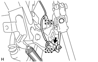
5. REMOVE PUSH ROD PIN (a) Remove the clip and push rod pin. 6. REMOVE STOP LIGHT SWITCH ASSEMBLY 7. REMOVE STOP LIGHT SWITCH MOUNTING ADJUSTER (a) Remove the stop light switch mounting adjuster. 8. DISCONNECT BRAKE PEDAL SUPPORT ASSEMBLY
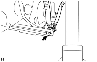
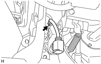
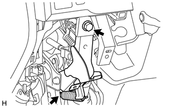
(b) Disconnect the 2 clamps from the brake pedal support assembly.
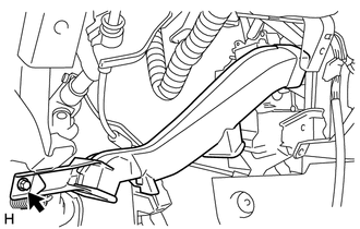
(f) Remove the bolt, and disconnect the brake pedal support assembly from the instrument panel reinforcement assembly. 9. REMOVE INSTRUMENT PANEL REINFORCEMENT ASSEMBLY Click here
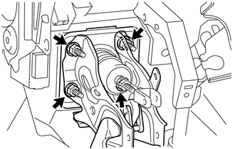
10. REMOVE BRAKE PEDAL SUPPORT ASSEMBLY
11. REMOVE BRAKE PEDAL PAD (a) Remove the brake pedal pad. |
Toyota Tundra Service Manual > Ultrasonic Sensor(for Rear Side): Inspection
INSPECTION PROCEDURE 1. INSPECT NO. 2 ULTRASONIC SENSOR (a) Measure the resistance according to the value(s) in the table below. Standard Resistance: Tester Connection Condition Specified Condition 1 (BI) - 5 (EI) Always 10 kΩ or higher 1 (BI) - 2 (BO) Always 10 kΩ or higher 3 (SI) - 4 (SO) Always ...

 ).
).