Components COMPONENTS ILLUSTRATION 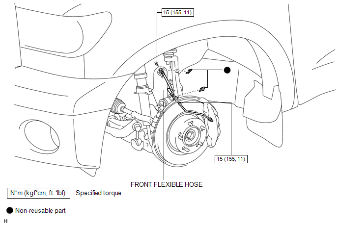 Installation INSTALLATION CAUTION / NOTICE / HINT HINT:
PROCEDURE 1. INSTALL FRONT FLEXIBLE HOSE
(b) Using a union nut wrench, connect the flexible hose to the brake tube and wheel cylinder tube while holding the flexible hose with a wrench. Torque: 15 N·m {155 kgf·cm, 11 ft·lbf} NOTICE:
2. BLEED BRAKE LINE 3. INSTALL FRONT WHEEL Torque: for Aluminum Wheel : 131 N·m {1336 kgf·cm, 97 ft·lbf} for Steel Wheel : 209 N·m {2131 kgf·cm, 154 ft·lbf} Removal REMOVAL CAUTION / NOTICE / HINT HINT:
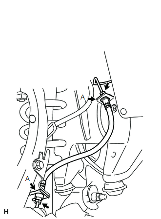
PROCEDURE 1. REMOVE FRONT WHEEL 2. DRAIN BRAKE FLUID NOTICE: Wash off brake fluid immediately if it comes in contact with any painted surface. 3. REMOVE FRONT FLEXIBLE HOSE  (a) Remove the brake tube and wheel cylinder tube from the flexible hose with a union nut wrench while holding the flexible hose with a wrench. NOTICE:
(b) Remove the 2 clips (labeled A) and flexible hose. |
Toyota Tundra Service Manual > Cylinder Head: Disassembly
DISASSEMBLY PROCEDURE 1. REMOVE INTAKE VALVE (a) Using SST and wooden blocks, compress the compression spring and remove the valve spring retainer locks. SST: 09202-70020 09202-01010 09202-01020 SST: 09202-00021 (b) Remove the retainer, compression spring and valve. HINT: Arrange the removed parts i ...