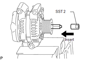
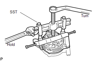
DISASSEMBLY PROCEDURE 1. REMOVE GENERATOR PULLEY 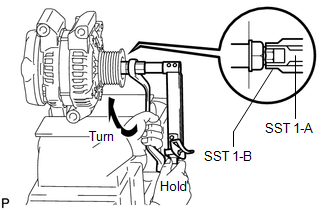 SST: 09820-63011 09820-06010 09820-06021
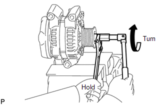
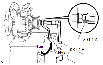
(a) Clamp the generator housing stay in a vise. (b) Install SST 1-A to the pulley shaft. (c) Install SST 1-B to SST 1-A. (d) Hold SST 1-A with a torque wrench, and tighten SST 1-B clockwise to the specified torque. Torque: 39 N·m {398 kgf·cm, 29 ft·lbf} NOTICE: Check that SST is secured on the rotor shaft.
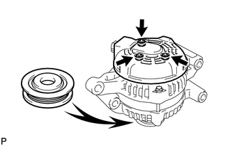
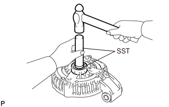
(g) Remove SST 2 from the generator.
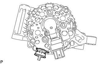
(i) Remove the pulley nut and pulley. 2. REMOVE GENERATOR REAR END COVER
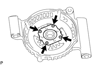
(b) Remove the 3 nuts and end cover.
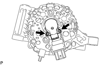
3. REMOVE GENERATOR BRUSH HOLDER ASSEMBLY
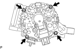
4. REMOVE GENERATOR COIL ASSEMBLY
(c) Remove the generator washer. 5. REMOVE GENERATOR ROTOR ASSEMBLY 6. REMOVE GENERATOR DRIVE END FRAME BEARING
|
Toyota Tundra Service Manual > Lighting System: DRL Relay Circuit
DESCRIPTION The main body ECU (multiplex network body ECU) controls the daytime running lights. WIRING DIAGRAM CAUTION / NOTICE / HINT NOTICE: Inspect the fuses for circuits related to this system before performing the following procedure. PROCEDURE 1. PERFORM ACTIVE TEST USING TECHSTREAM (a) Using ...