REMOVAL PROCEDURE 1. DISCONNECT FRONT FENDER LINER RH (See page HINT: It is not necessary to fully remove the front fender liner RH. Partially remove it so that the air pump assembly with bracket can be removed in a later step. 2. DISCONNECT FRONT FENDER APRON SEAL RH
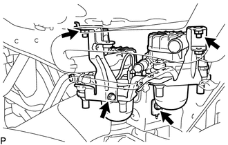
3. REMOVE NO. 2 AIR INJECTION SYSTEM HOSE
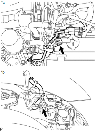
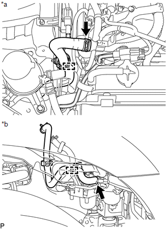
(b) Front Fender RH Inside: (1) Slide the clamp and disconnect the No. 2 air injection system hose from the air pump assembly. 4. REMOVE NO. 3 AIR INJECTION SYSTEM HOSE
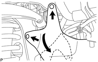
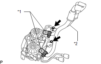
(b) Front Fender RH Inside: (1) Detach the clamp. (2) Slide the clamp indicated by the arrow in the illustration and disconnect the No. 3 air injection system hose from the air pump assembly. 5. REMOVE AIR PUMP ASSEMBLY WITH BRACKET
6. REMOVE AIR PUMP INLET
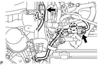
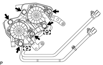
7. REMOVE NO. 1 AIR INJECTION SYSTEM HOSE (a) Remove the 2 No. 1 air injection system hoses from the 2 air pump assemblies. 8. REMOVE AIR PUMP ASSEMBLY
(b) Disconnect the 6 air pump insulators. |
Toyota Tundra Service Manual > Rear Seat Assembly(for Crewmax Lh Side): Installation
INSTALLATION PROCEDURE 1. INSTALL REAR OUTER SEAT LEG BRACKET SUB-ASSEMBLY RH (a) Install rear outer seat leg bracket sub-assembly RH with the 2 bolts. Torque: 42 N·m {428 kgf·cm, 31 ft·lbf} 2. INSTALL REAR INNER SEAT LEG BRACKET SUB-ASSEMBLY RH (a) Install rear inner seat leg bracket sub-assembl ...

 )
)