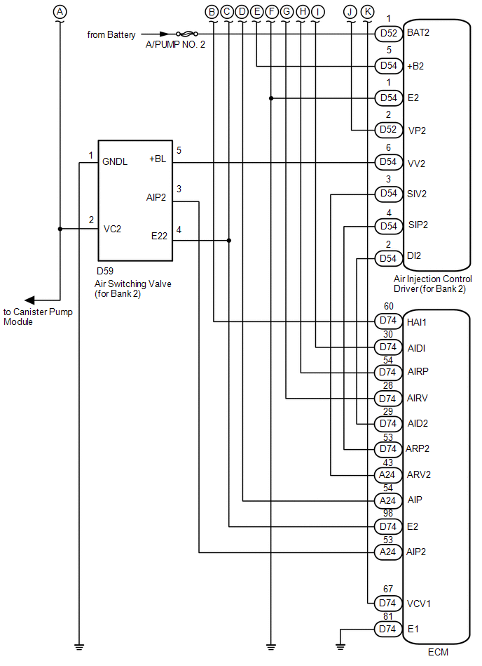
SYSTEM DIAGRAM 1. SECONDARY AIR INJECTION CONTROL SYSTEM DIAGRAM 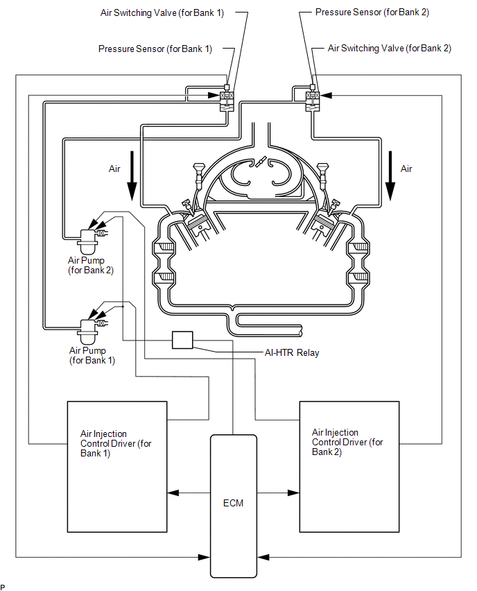 2. SECONDARY AIR INJECTION SYSTEM WIRING DIAGRAM 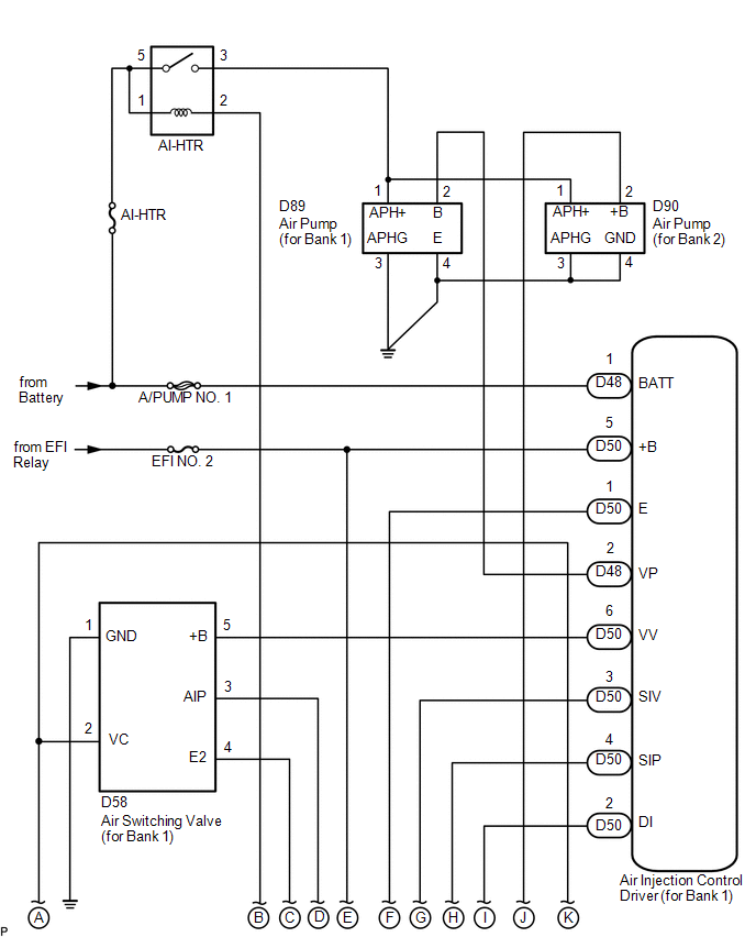
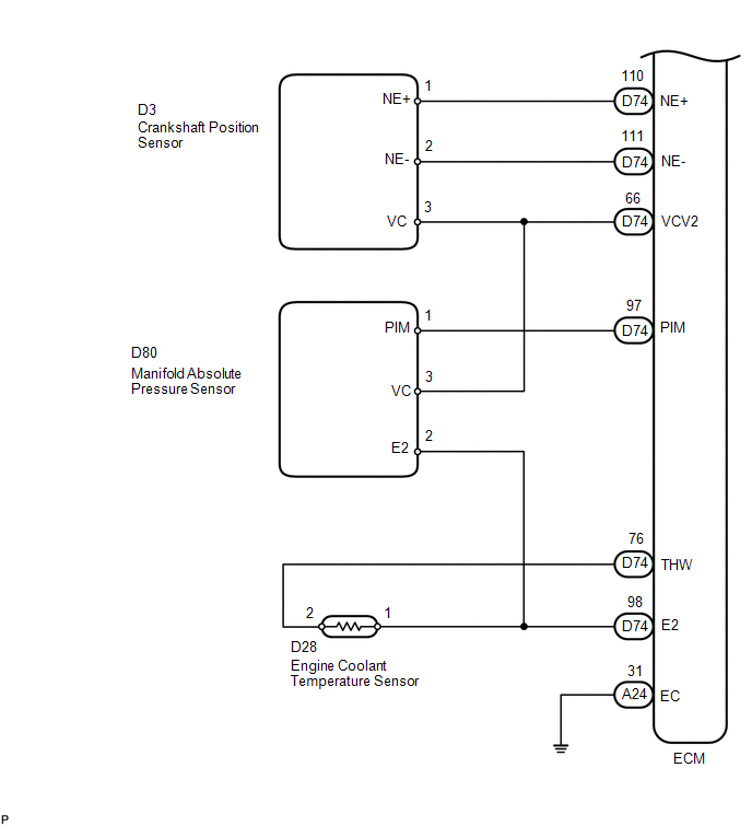
 3. EGR CONTROL SYSTEM DIAGRAM 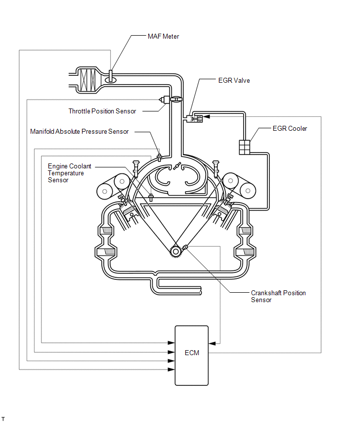 4. EGR CONTROL SYSTEM WIRING DIAGRAM 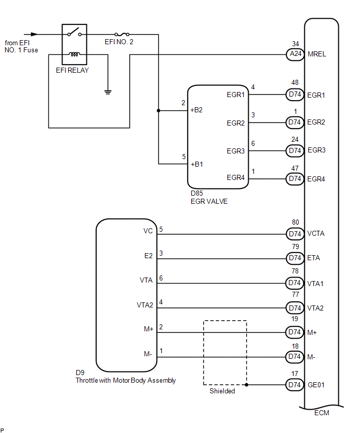
 5. EVAP CONTROL SYSTEM DIAGRAM 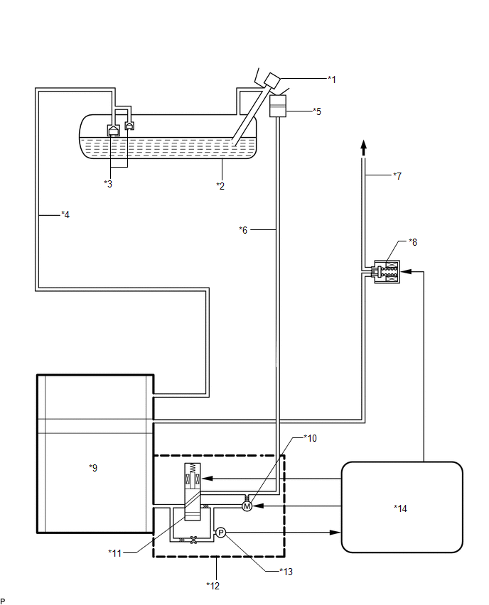 Text in Illustration Text in Illustration
6. EVAP CONTROL SYSTEM WIRING DIAGRAM 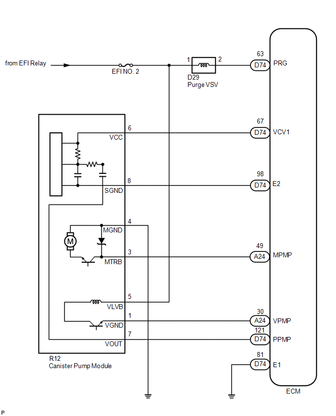 |
Toyota Tundra Service Manual > Ignition Key Cylinder Light: Inspection
INSPECTION PROCEDURE 1. INSPECT TRANSPONDER KEY COIL (IGNITION KEY CYLINDER LIGHT) (a) Apply battery voltage to the connector and check the light illumination condition. OK: Condition Specified Condition Battery positive (+) → Terminal 2 (ILL+) Battery negative (-) → Terminal 4 (ILL-) Illuminate ...


