REMOVAL CAUTION / NOTICE / HINT CAUTION:
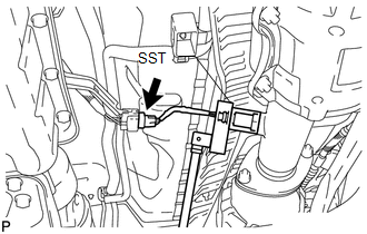
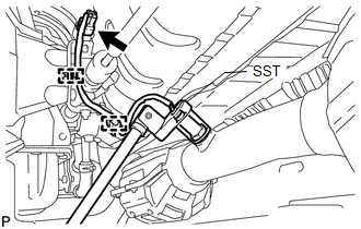
PROCEDURE 1. REMOVE PROPELLER SHAFT HEAT INSULATOR 2. REMOVE HEATED OXYGEN SENSOR (for Bank 1 Sensor 2) (a) Disconnect the heated oxygen sensor connector.
3. REMOVE HEATED OXYGEN SENSOR (for Bank 2 Sensor 2)
(b) Using SST, remove the heated oxygen sensor. SST: 09224-00010 |
Toyota Tundra Service Manual > Back Window Glass(for Double Cab): Inspection
INSPECTION PROCEDURE 1. INSPECT POWER WINDOW REGULATOR MOTOR ASSEMBLY (for Power Slide Type) *a Component without harness connected (Power Window Regulator Motor Assembly) *b Clockwise *c Counterclockwise *d Motor Gear (a) Check the operation of the power window regulator motor assembly. (1) Apply b ...