Components COMPONENTS ILLUSTRATION 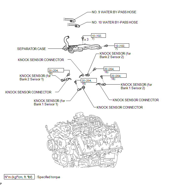 Inspection INSPECTION PROCEDURE 1. INSPECT KNOCK SENSOR 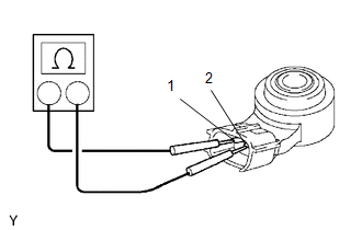 (a) Measure the resistance according to the value(s) in the table below. Standard Resistance:
If the result is not as specified, replace the knock sensor. Installation INSTALLATION CAUTION / NOTICE / HINT HINT: Perform "Inspection After Repairs" after replacing the knock sensor (See page
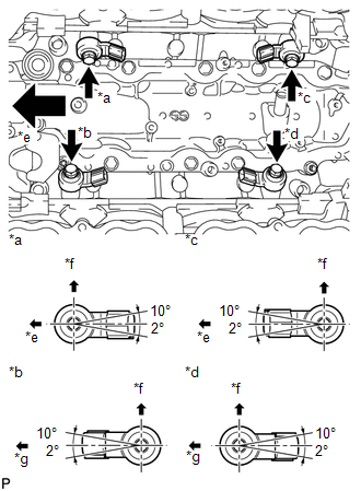
PROCEDURE 1. INSTALL KNOCK SENSOR HINT: Perform "Inspection After Repairs" after replacing the knock sensor (See page
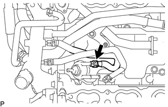
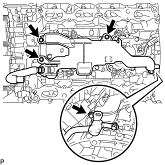
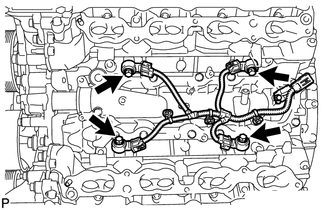
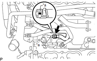
(b) Connect the 4 knock sensor connectors. 2. INSTALL SEPARATOR CASE (a) Install the separator case with the 4 bolts. Torque: 10 N·m {102 kgf·cm, 7 ft·lbf} 3. CONNECT NO. 9 WATER BY-PASS HOSE
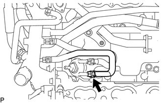
4. CONNECT NO. 10 WATER BY-PASS HOSE
5. INSTALL INTAKE MANIFOLD (See page Removal REMOVAL PROCEDURE 1. REMOVE INTAKE MANIFOLD (See page 2. DISCONNECT NO. 10 WATER BY-PASS HOSE
3. DISCONNECT NO. 9 WATER BY-PASS HOSE
4. REMOVE SEPARATOR CASE
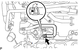
5. REMOVE KNOCK SENSOR
(b) Remove the 4 bolts and 4 knock sensors. |
Toyota Tundra Service Manual > Forward Recognition Camera System: Lost Communication with Cruise Control Front Distance Range Sensor (U0235)
DESCRIPTION The forward recognition camera communicates with the millimeter wave radar sensor assembly via CAN communication. If there is a communication error with the millimeter wave radar sensor assembly, the forward recognition camera stores DTC U0235. DTC No. Detection Item DTC Detection Condit ...

 ).
).
 )
)