DESCRIPTION HINT: Refer to DTC P2195 (See page
 ). ). |
DTC No. | DTC Detection Condition |
Trouble Area | | P014C |
The "Rich to Lean response rate deterioration level*" value is less than the standard.
(2 trip detection logic) |
- Air fuel ratio sensor (for bank 1 sensor 1)
- Air fuel ratio sensor (for bank 1 sensor 1) heater
- ECM
| | P014D |
The "Lean to Rich response rate deterioration level*" value is more than the standard.
(2 trip detection logic) | |
P014E | The "Rich to Lean response rate deterioration level*" value is less than the standard.
(2 trip detection logic) |
- Air fuel ratio sensor (for bank 2 sensor 1)
- Air fuel ratio sensor (for bank 2 sensor 1) heater
- ECM
| | P014F |
The "Lean to Rich response rate deterioration level*" value is more than the standard.
(2 trip detection logic) | |
P015A | The "Rich to Lean delay level*" value is less than the standard.
(2 trip detection logic) |
- Air fuel ratio sensor (for bank 1 sensor 1)
- Air fuel ratio sensor (for bank 1 sensor 1) heater
- ECM
| | P015B |
The "Lean to Rich delay level*" value is more than the standard.
(2 trip detection logic) | |
P015C | The "Rich to Lean delay level*" value is less than the standard.
(2 trip detection logic) |
- Air fuel ratio sensor (for bank 2 sensor 1)
- Air fuel ratio sensor (for bank 2 sensor 1) heater
- ECM
| | P015D |
The "Lean to Rich delay level*" value is more than the standard.
(2 trip detection logic) | *: Calculated by the ECM based on the air fuel ratio sensor output MONITOR DESCRIPTION
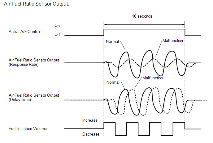
After
the engine is warm, the ECM carries out air-fuel ratio feedback
control, and maintains the air-fuel ratio at the stoichiometric level.
In addition, after all the preconditions have been met, active air-fuel
ratio control is carried out for approx. 10 seconds, and during active
air-fuel ratio control, the ECM measures the response of the air fuel
ratio sensor by increasing or decreasing the injection volume by a
specific quantity based on the stoichiometric air-fuel ratio learned
during normal air-fuel control. The ECM determines whether there is an
air fuel ratio sensor malfunction at the mid-point of active air-fuel
ratio control. If the air fuel ratio sensor's response ability is reduced, DTC P014C, P014D, P014E and P014F are stored.
If the time it takes the air fuel ratio sensor output to change is delayed, DTC P015A, P015B, P015C and P015D are stored.
 MONITOR STRATEGY |
Related DTCs | P014C: Air fuel ratio sensor (bank 1) slow response (rich to lean)
P014D: Air fuel ratio sensor (bank 1) slow response (lean to rich)
P014E: Air fuel ratio sensor (bank 2) slow response (rich to lean)
P014F: Air fuel ratio sensor (bank 2) slow response (lean to rich)
P015A: Air fuel ratio sensor (bank 1) delayed response (rich to lean)
P015B: Air fuel ratio sensor (bank 1) delayed response (lean to rich)
P015C: Air fuel ratio sensor (bank 2) delayed response (rich to lean)
P015D: Air fuel ratio sensor (bank 2) delayed response (lean to rich) | |
Required Sensors/Components (Main) | Air fuel ratio sensor | |
Required Sensors/Components (Related) |
Vehicle speed sensor, crankshaft position sensor | |
Frequency of Operation | Once per driving cycle | |
Duration | 10 to 15 seconds | |
MIL Operation | 2 driving cycles | |
Sequence of Operation | None | TYPICAL ENABLING CONDITIONS |
Monitor runs whenever following DTCs not stored |
P0016, P0018 (VVT system - Misalignment) P0017, P0019 (Exhaust VVT system - Misalignment)
P0031, P0032, P0051, P0052, P101D, P103D (Air fuel ratio sensor heater)
P006A, P0107, P0108 (Manifold absolute pressure) P0102, P0103 (Mass air flow meter)
P0112, P0113 (Intake air temperature sensor) P0115, P0117, P0118 (Engine coolant temperature sensor)
P0120, P0121, P0122, P0123, P0220, P0222, P0223, P2135 (Throttle position sensor)
P0125 (Insufficient Coolant Temperature for Closed Loop Fuel Control)
P0128 (Thermostat) P0171, P0172, P0174, P0175 (Fuel system)
P0301 - P0308 (Misfire) P0335 (Crankshaft position sensor) P1340 (Camshaft position sensor)
P0401 (EGR system) P0412, P0415, P0418, P0419, P1613, P1614 (Secondary Air Injection System Control)
P0451, P0452, P0453 (Evaporative Emission System Pressure Sensor) P0500 (Vehicle speed sensor)
P0505 (IAC valve) P219A, P219B, P219C, P219D, P219E, P219F, P21A0, P21A1, P21A2, P21A3 (Air-fuel ratio imbalance)
P2440, P2441, P2442, P2443, P2444, P2445, P2446, P2447 (Secondary Air Injection System) | |
Active air fuel ratio control | Performing | |
Active air fuel ratio control is performed when the following conditions met |
- | | Battery voltage |
11 V or higher | | Engine coolant temperature |
75°C (167°F) or higher | | Idle |
OFF | | Engine speed |
1000 to 2500 rpm | | Air fuel ratio sensor status |
Activated | | Fuel-cut |
OFF | | Engine load |
10 to 70% | | Shift position |
2nd or higher | | Catalyst monitor |
Not executed | | Mass air flow |
4.0 to 12 gm/sec. | TYPICAL MALFUNCTION THRESHOLDS Air Fuel Ratio Sensor Slow Response (Rich to Lean) |
Rich to Lean response rate deterioration level |
0.03 V or less | Air Fuel Ratio Sensor Slow Response (Lean to Rich) |
Lean to Rich response rate deterioration level |
-0.035 V or higher | Air Fuel Ratio Sensor Delayed Response (Rich to Lean) |
Rich to Lean delay level | 376.832 ms or more | Air Fuel Ratio Sensor Delayed Response (Lean to Rich) |
Lean to Rich delay level | 376.832 ms or more | MONITOR RESULT
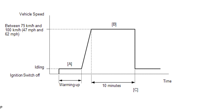
Refer to Checking Monitor Status (See page ). CONFIRMATION DRIVING PATTERN
HINT: Performing this confirmation driving pattern will activate the air fuel ratio sensor response monitor.
- Connect the Techstream to the DLC3.
- Turn the ignition switch to ON.
- Turn the Techstream on.
- Clear DTCs (even if no DTCs are stored, perform the clear DTC operation).
- Turn the ignition switch off and wait for at least 30 seconds.
- Turn the ignition switch to ON and turn the Techstream on.
- Enter the following menus: Powertrain / Engine and ECT / Monitor / O2 Sensor.
- Check that the monitor item O2 Sensor is Incomplete.
HINT:
The
test values for the test items RL RES RATE B1S1, LR RES RATE B1S1, RL
DELAY B1S1, LR DELAY B1S1, RL RES RATE B2S1, LR RES RATE B2S1, RL DELAY
B2S1 and LR DELAY B2S1 do not exist in the Detail of O2 Sensor monitor
at this time (the initial value of "0.000" is indicated for each test
item).
- Start the engine and warm it up until the engine coolant temperature is 75°C (167°F) or higher [A].
- Drive the vehicle at a constant speed of between 75 and 100 km/h (47 and 62 mph) for 10 minutes [B].
- Check that the monitor item O2 Sensor becomes Complete.
HINT:
Check
the test values on the Techstream by entering the following menus:
Powertrain / Engine and ECT / Monitor / O2 Sensor /Details / RL RES RATE
B1S1, LR RES RATE B1S1, RL DELAY B1S1, LR DELAY B1S1, RL RES RATE B2S1,
LR RES RATE B2S1, RL DELAY B2S1 and LR DELAY B2S1.
- If the monitor item O2 Sensor does not become Complete (if the test
values indicated on the Techstream do not change), perform Readiness
Monitor Drive Pattern for the air fuel ratio sensor and heated oxygen
sensor (See page ).
- Enter the following menus: Powertrain / Engine and ECT / Trouble Codes [C].
- Read the pending DTCs.
HINT:
- If a pending DTC is output, the system is malfunctioning.
- If a pending DTC is not output, perform the following procedure.
- Enter the following menus: Powertrain / Engine and ECT / Utility / All Readiness.
- Input the DTC: P014C, P014D, P014E, P014F, P015A, P015B, P015C or P015D.
- Check the DTC judgment result.
|
Tester Display |
Description |
|
NORMAL |
- DTC judgment completed
- System normal
|
|
ABNORMAL |
- DTC judgment completed
- System abnormal
|
|
INCOMPLETE |
- DTC judgment not completed
- Perform driving pattern after confirming DTC enabling conditions
|
|
N/A |
- Unable to perform DTC judgment
- Number of DTCs which do not fulfill DTC preconditions has reached ECU memory limit
|
HINT:
If the judgment result shows ABNORMAL, the system has a malfunction.
- If the test result is INCOMPLETE or N/A and no pending DTC is output,
perform a universal trip and check for permanent DTCs (See page
).
HINT:
- If a permanent DTC is output, the system is malfunctioning.
- If no permanent DTC is output, the system is normal.
WIRING DIAGRAM Refer to DTC P2195 (See page
). CAUTION / NOTICE / HINT
HINT:
PROCEDURE |
1. | CHECK FOR ANY OTHER DTCS OUTPUT (IN ADDITION TO DTC P014C, P014D, P014E, P014F, P015A, P015B, P015C OR P015D) |
(a) Connect the Techstream to the DLC3. (b) Turn the ignition switch to ON.
(c) Turn the Techstream on. (d) Enter the following menus: Powertrain / Engine and ECT / Trouble Codes.
(e) Read the DTCs. Result |
Result | Proceed to | |
DTC P014C, P014D, P014E, P014F, P015A, P015B, P015C or P015D is output |
A | | DTC P014C, P014D, P014E, P014F, P015A, P015B, P015C or P015D and other DTCs are output |
B | HINT: If any DTCs other than P014C, P014D, P014E, P014F, P015A, P015B, P015C or P015D are output, troubleshoot those DTCs first.
| B |
 | GO TO DTC CHART |
|
A |
 | |
| 2. |
INSPECT AIR FUEL RATIO SENSOR (HEATER RESISTANCE) |
(a) Inspect the air fuel ratio sensor (See page
). HINT: Perform "Inspection After Repair" after replacing the air fuel ratio sensor (See page
).
| NG | |
REPLACE AIR FUEL RATIO SENSOR |
|
OK | |
| |
| 3. |
CHECK HARNESS AND CONNECTOR (AIR FUEL RATIO SENSOR - ECM) |
| NG |
| REPAIR OR REPLACE HARNESS OR CONNECTOR |
|
OK | |
| |
| 4. |
CHECK AIR FUEL RATIO SENSOR | (a) Check that the proper air fuel ratio sensor is installed to the vehicle.
HINT: Perform "Inspection After Repair" after replacing the air fuel ratio sensor (See page
).
| NG | |
REPLACE AIR FUEL RATIO SENSOR |
|
OK | |
| |
| 5. |
PERFORM CONFIRMATION DRIVING PATTERN | (a) Drive the vehicle according to Confirmation Driving Pattern.
|
NEXT | |
| |
| 6. |
CHECK WHETHER DTC OUTPUT RECURS (DTC P014C, P014D, P014E, P014F, P015A, P015B, P015C OR P015D) |
(a) Connect the Techstream to the DLC3. (b) Turn the ignition switch to ON.
(c) Turn the Techstream on. (d) Enter the following menus: Powertrain / Engine and ECT / Trouble Codes / Pending.
(e) Read the DTCs. Result |
Result | Proceed to | |
DTC P014C, P014D, P014E, P014F, P015A, P015B, P015C or P015D is output |
A | | DTC is not output |
B |
| B |
| CHECK FOR INTERMITTENT PROBLEMS |
|
A | |
| |
| 7. |
REPLACE AIR FUEL RATIO SENSOR | (a) Replace the air fuel ratio sensor (See page
). HINT: Perform "Inspection After Repair" after replacing the air fuel ratio sensor (See page
).
|
NEXT | |
| |
| 8. |
PERFORM CONFIRMATION DRIVING PATTERN | (a) Drive the vehicle according to Confirmation Driving Pattern.
|
NEXT | |
| |
| 9. |
CHECK WHETHER DTC OUTPUT RECURS (DTC P014C, P014D, P014E, P014F, P015A, P015B, P015C or P015D) |
(a) Connect the Techstream to the DLC3. (b) Turn the ignition switch to ON.
(c) Turn the Techstream on. (d) Enter the following menus: Powertrain / Engine and ECT / Trouble Codes / Pending.
(e) Read the DTCs. Result |
Result | Proceed to | |
DTC is not output | A | |
DTC P014C, P014D, P014E, P014F, P015A, P015B, P015C or P015D is output |
B |
| A |
| END |
| B |
| CHECK ENGINE TO DETERMINE CAUSE OF EXTREMELY RICH OR LEAN ACTUAL AIR FUEL RATIO | |


