DESCRIPTION While the
engine is being cranked, the positive battery voltage is applied to
terminal STA of the ECM. If the ECM detects the Starter Control (STA)
signal while the vehicle is being driven, it determines that there is a
malfunction in the STA circuit. The ECM then illuminates the MIL and
stores the DTC. This monitor runs when the vehicle is driven at 20 km/h (12.4 mph) or more for over 20 seconds. |
DTC No. | DTC Detection Condition |
Trouble Area | | P0617 |
When
conditions (a), (b) and (c) met, positive (+B) battery voltage of 10.5 V
or more applied to ECM for 20 seconds (1 trip detection logic)
- (a) Vehicle speed 20 km/h (12.4 mph) or more
- (b) Engine speed 1000 rpm or more
- (c) STA signal ON
|
- Park/Neutral Position (PNP) switch
- Starter relay circuit
- Ignition switch assembly
- ECM
| MONITOR STRATEGY |
Related DTCs | P0617: Starter signal | |
Required Sensors/Components (Main) | ST relay, PNP switch and ignition switch | |
Required Sensors/Components (Related) |
Vehicle Speed Sensor (VSS), Crankshaft Position (CKP) sensor | |
Frequency of Operation | Continuous | |
Duration | 20 seconds | |
MIL Operation | Immediate | |
Sequence of Operation | None | TYPICAL ENABLING CONDITIONS |
Monitor runs whenever following DTCs not present |
None | | Battery voltage |
10.5 V or more | | Vehicle speed |
20 km/h (12.43 mph) or more | |
Engine speed | 1000 rpm or more | TYPICAL MALFUNCTION THRESHOLDS CONFIRMATION DRIVING PATTERN
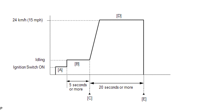
- Connect the Techstream to the DLC3.
- Turn the ignition switch to ON and turn the Techstream on.
- Clear the DTCs (even if no DTCs are stored, perform the clear DTC operation).
- Turn the ignition switch off and wait for at least 30 seconds.
- Turn the ignition switch to ON and turn the Techstream on [A].
- Idle the engine for 5 seconds or more [B].
- Enter the following menus: Powertrain / Engine and ECT / Trouble Codes [C].
- Read the pending DTCs.
HINT:
- If a pending DTC is output, the system is malfunctioning.
- If a pending DTC is not output, perform the following procedure.
- Enter the following menus: Powertrain / Engine and ECT / Utility / All Readiness.
- Input the DTC: P0617.
- Check the DTC judgment result.
|
Tester Display |
Description |
|
NORMAL |
- DTC judgment completed
- System normal
|
|
ABNORMAL |
- DTC judgment completed
- System abnormal
|
|
INCOMPLETE |
- DTC judgment not completed
- Perform driving pattern after confirming DTC enabling conditions
|
|
N/A |
- Unable to perform DTC judgment
- Number of DTCs which do not fulfill DTC preconditions has reached ECU memory limit
|
HINT:
- If the judgment result shows ABNORMAL, the system has a malfunction.
- If the judgment result shows INCOMPLETE or N/A, perform steps [D] and [E].
- Drive the vehicle at 24 km/h (15 mph) or more for 20 seconds or more [D].
CAUTION:
When performing the confirmation driving pattern, obey all speed limits and traffic laws.
- Check the DTC judgment result [E].
- If the test result is INCOMPLETE or N/A and no pending DTC is output,
perform a universal trip and check for permanent DTCs (See page
 ). ).
HINT:
- If a permanent DTC is output, the system is malfunctioning.
- If no permanent DTC is output, the system is normal.
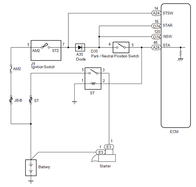
WIRING DIAGRAM
 CAUTION / NOTICE / HINT
HINT:
PROCEDURE |
1. | READ VALUE USING TECHSTREAM (STARTER SIGNAL) |
(a) Connect the Techstream to the DLC3. (b) Turn the ignition switch to ON.
(c) Turn the Techstream on. (d) Enter the following menus: Powertrain / Engine and ECT / Data List / Starter Signal.
(e) Check the value displayed on the Techstream when the ignition switch is turned to the ON and START positions.
OK: |
Ignition Switch Position |
Starter Signal | |
ON | OFF | |
START | ON |
| OK |
 | CHECK FOR INTERMITTENT PROBLEMS |
|
NG |
 | |
| 2. |
READ VALUE USING TECHSTREAM (STARTER SIGNAL) |
(a) Disconnect the Park/Neutral Position (PNP) switch connector. (b) Connect the Techstream to the DLC3.
(c) Turn the ignition switch to ON. (d) Turn the Techstream on.
(e) Enter the following menus: Powertrain / Engine and ECT / Data List / Starter Signal.
(f) Check the value displayed on the Techstream when the ignition switch is turned to the ON and START positions. Result |
Starter Signal | Proceed to | |
Remains ON | A | |
OFF | B |
| B |
| GO TO STEP 4 |
|
A | |
| |
| 3. |
INSPECT ECM (STA TERMINAL VOLTAGE) | (a) Disconnect the ECM connector.
(b) Disconnect the PNP switch connector. (c) Turn the ignition switch to ON.
(d) Measure the voltage according to the value(s) in the table below. Standard Voltage: |
Tester Connection | Condition |
Specified Condition | Proceed to | |
A24-46 (STA) - Body ground |
Ignition switch ON | Below 1.5 V |
A | | 11 to 14 V |
B |
| A |
| REPLACE ECM |
| B |
| REPAIR OR REPLACE HARNESS OR CONNECTOR (ECM - PNP SWITCH - ST RELAY) |
| 4. |
INSPECT PARK/NEUTRAL POSITION SWITCH ASSEMBLY |
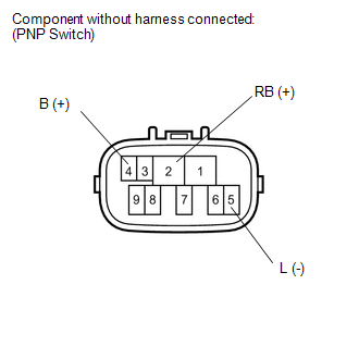 (a) Disconnect the PNP switch connector.
(b) Measure the resistance according to the value(s) in the table below.
Standard Resistance: |
Tester Connection | Condition |
Specified Condition | |
4 (B) - 5 (L) | Except P or N |
10 kΩ or higher | |
2 (RB) - 5 (L) | All positions |
10 kΩ or higher | Result |
Result | Proceed to | |
Short between 4 and 5 |
A | | Short between 2 and 5 |
B | | Within standard range |
C |
| B |
| REPLACE PARK/NEUTRAL POSITION SWITCH ASSEMBLY |
| C |
| GO TO STEP 6 |
|
A | |
| |
| 5. |
REPLACE PARK/NEUTRAL POSITION SWITCH ASSEMBLY |
(a) Replace the park/neutral position switch.
- for 2WD (See page )
- for 4WD (See page )
|
NEXT | |
| |
| 6. |
INSPECT IGNITION SWITCH ASSEMBLY |
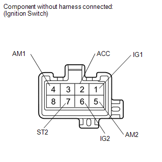 (a) Disconnect the ignition switch assembly connector.
(b) Measure the resistance according to the value(s) in the table below.
Standard Resistance: |
Tester Connection | Switch Condition |
Specified Condition | |
5 (AM2) - 7 (ST2) | Ignition switch position not START |
10 kΩ or higher | |
Ignition switch position START |
Below 1 Ω |
| NG |
| REPLACE IGNITION SWITCH ASSEMBLY |
|
OK | |
| |
| 7. |
READ VALUE USING TECHSTREAM (STARTER SIGNAL) |
(a) Connect the Techstream to the DLC3. (b) Turn the ignition switch to ON.
(c) Turn the Techstream on. (d) Enter the following menus: Powertrain / Engine and ECT / Data List / Starter Signal.
(e) Check the value displayed on the Techstream when the ignition switch is turned to the ON and START positions.
OK: |
Ignition Switch Position |
Starter Signal | |
ON | OFF | |
START | ON | Result |
Result | Proceed to | |
NG | A | |
OK | B |
| B |
| CHECK FOR INTERMITTENT PROBLEMS |
|
A | |
| |
| 8. |
REPAIR OR REPLACE HARNESS OR CONNECTOR (PNP SWITCH - STA TERMINAL OF ECM) |
|
NEXT | |
| |
| 9. |
CHECK WHETHER DTC OUTPUT RECURS | (a) Connect the Techstream to the DLC3.
(b) Turn the ignition switch to ON. (c) Turn the Techstream on.
(d) Clear DTCs (See page ). (e) Drive the vehicle at more than 20 km/h (12.43 mph) for over 20 seconds.
(f) Enter the following menus: Powertrain / Engine and ECT / Trouble Codes.
(g) Read DTCs. Result |
Result | Proceed to | |
P0617 is output | A | |
No DTC is output | B |
| A |
| REPLACE ECM |
| B |
| END | | 

