DESCRIPTION The purpose of
this circuit is to prevent the engine from stalling while driving in the
lock-up condition when the brakes are suddenly applied. When
the brake pedal is depressed, this switch sends a signal to the ECM.
Then the ECM cancels the operation of the lock-up clutch while braking
is in progress. |
DTC No. | DTC Detection Condition |
Trouble Area | | P0724 |
Stop
light switch remains ON even when vehicle is driven in GO (30 km/h
(18.63 mph) or more) and STOP (less than 3 km/h (1.86 mph)) pattern 5
times (2 trip detection logic) |
- Short in stop light switch signal circuit
- Stop light switch
- ECM
| MONITOR DESCRIPTION
This
DTC indicates that the stop light switch remains ON. When the stop
light switch remains ON during GO and STOP driving, the ECM interprets
this as a fault in the stop light switch. Then the MIL illuminates and
the ECM stores the DTC. The vehicle must GO (30 km/h (18.63 mph) or
more) and STOP (less than 3 km/h (1.86 mph)) 5 times for 2 driving
cycles in order for the DTC to be output. MONITOR STRATEGY |
Related DTCs | P0724: Stop light switch/Range check/Rationality | |
Required sensors/Components | Stop light switch, Vehicle speed sensor | |
Frequency of operation | Continuous | |
Duration | GO and STOP 5 times | |
MIL operation | 2 driving cycles | |
Sequence of operation | None | TYPICAL ENABLING CONDITIONS |
Monitor runs whenever following DTCs not present | None | |
Battery voltage | 8 V or more | |
Starter | OFF | | Ignition switch |
ON | | GO: Vehicle speed | 30 km/h (18.65 mph) or more | |
STOP: Vehicle speed | Less than 3 km/h (1.86 mph) | TYPICAL MALFUNCTION THRESHOLDS |
Stop light switch | Stuck ON | CONFIRMATION DRIVING PATTERN
- Connect the Techstream to the DLC3.
- Turn the ignition switch to ON and turn the Techstream on.
- Clear DTCs (even if no DTCs are stored, perform the clear DTC operation).
- Turn the ignition switch off and wait for at least 30 seconds.
- Turn the ignition switch to ON and turn the Techstream on [A].
- Wait 5 seconds.
- Enter the following menus: Powertrain / Engine and ECT / Trouble Codes [B].
- Read the pending DTCs.
HINT:
- If a pending DTC is output, the system is malfunctioning.
- If a pending DTC is not output, perform the following procedure.
- Enter the following menus: Powertrain / Engine and ECT / Utility / All Readiness.
- Input the DTC: P0724.
- Check the DTC judgment result.
|
Tester Display |
Description |
|
NORMAL |
- DTC judgment completed
- System normal
|
|
ABNORMAL |
- DTC judgment completed
- System abnormal
|
|
INCOMPLETE |
- DTC judgment not completed
- Perform driving pattern after confirming DTC enabling conditions
|
|
N/A |
- Unable to perform DTC judgment
- Number of DTCs which do not fulfill DTC preconditions has reached ECU memory limit
|
HINT:
- If the judgment result shows ABNORMAL, the system has a malfunction.
- If the judgment result shows INCOMPLETE or N/A, perform steps [C] through [E].
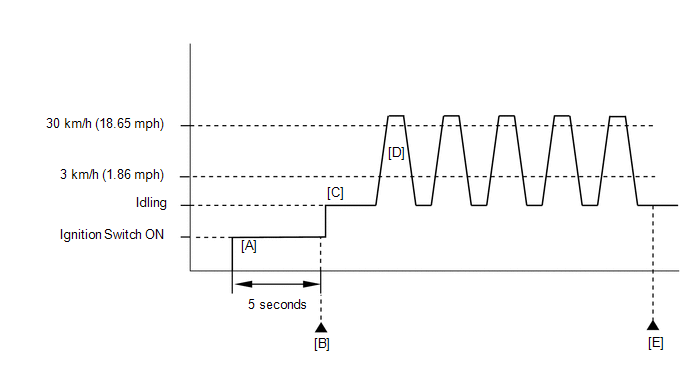
- Start the engine [C].
- Accelerate the vehicle to 30 km/h (19 mph) or more, depress the brake
pedal and decelerate the vehicle to 3 km/h (1.8 mph) or less [D]. Repeat
step [D] 5 times.
CAUTION:
When performing the confirmation driving pattern, obey all speed limits and traffic laws.
- Check the DTC judgment result [E].
- If the test result is INCOMPLETE or N/A and no pending DTC is output,
perform a universal trip and check for permanent DTCs (See page
 ). ).
HINT:
- If a permanent DTC is output, the system is malfunctioning.
- If no permanent DTC is output, the system is normal.
WIRING DIAGRAM Refer to DTC P0504 (See page
). CAUTION / NOTICE / HINT
HINT: Using
the Techstream to read the Data List allows switch, sensor, actuator
and other item values to be read without removing any parts. Reading the
Data List early in troubleshooting is one way to save time. NOTICE:
In
the table below, the values listed under "Normal Condition" are
reference values. Do not depend solely on these reference values when
deciding whether a part is faulty or not.
- Warm up the engine.
- Turn the ignition switch off.
- Connect the Techstream to the DLC3.
- Turn the ignition switch to ON.
- Turn the Techstream on.
- Enter the following menus: Powertrain / Engine and ECT / Data List.
- Follow the instructions on the Techstream and read the Data List.
|
Item | Measurement Item/
Range (Display) | Normal Condition |
Diagnostic Note | |
Stop Light Switch | Stop light switch status/
ON or OFF |
- Brake pedal is depressed: ON
- Brake pedal is released: OFF
| - | PROCEDURE
| 1. |
INSPECT STOP LIGHT SWITCH |
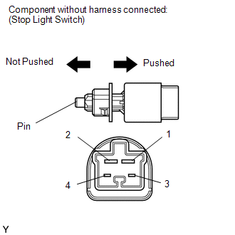 (a) Remove the stop light switch.
(b) Measure the resistance according to the value(s) in the table below.
Standard Resistance: |
Tester Connection | Switch Condition |
Specified Condition | |
1 - 2 | Pin not pushed |
Below 1 Ω | |
Pin pushed | 10 kΩ or higher | |
3 - 4 | Pin not pushed |
10 kΩ or higher | |
Pin pushed | Below 1 Ω |
| NG |
 | REPLACE STOP LIGHT SWITCH |
|
OK |
 | |
| 2. |
CHECK HARNESS AND CONNECTOR (ECM - BATTERY) |
| (a) Disconnect the ECM connector. | |
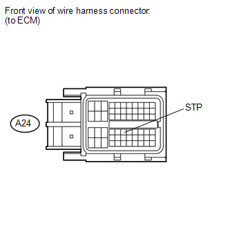
(b) Measure the voltage according to the value(s) in the table below. Standard Voltage: |
Tester Connection | Condition |
Specified Condition | |
A24-36 (STP) - Body ground |
Brake pedal is depressed |
11 to 14 V | |
A24-36 (STP) - Body ground |
Brake pedal is released |
Below 1 V |
| OK |
| REPLACE ECM |
| NG |
| REPAIR OR REPLACE HARNESS OR CONNECTOR | |