DESCRIPTION The Electronic Throttle Control System (ETCS) is composed of the throttle actuator, Throttle Position (TP) sensor, Accelerator Pedal Position (APP) sensor, and ECM. The ECM operates the throttle actuator to regulate the throttle valve in response to driver inputs. The TP sensor detects the opening angle of the throttle valve, and provides the ECM with feedback so that the throttle valve can be appropriately controlled by the ECM.
MONITOR DESCRIPTION The ECM determines the actual opening angle of the throttle valve from the TP sensor signal. The actual opening angle is compared to the target opening angle commanded by the ECM. If the difference between these two values is outside the standard range, the ECM interprets this as a malfunction in the ETCS. The ECM then illuminates the MIL and stores the DTC. If the malfunction is not repaired successfully, the DTC is stored when the accelerator pedal is quickly released (to close the throttle valve) after the engine speed reaches 5000 rpm by the accelerator pedal being fully depressed (fully open the throttle valve). MONITOR STRATEGY
TYPICAL ENABLING CONDITIONS
TYPICAL MALFUNCTION THRESHOLDS
CONFIRMATION DRIVING PATTERN 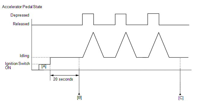
FAIL-SAFE When this DTC or other DTCs relating to ETCS (Electronic Throttle Control System) malfunctions are stored, the ECM enters fail-safe mode. During fail-safe mode, the ECM cuts the current to the throttle actuator and the throttle valve is returned to a 7° throttle angle by the return spring. The ECM then adjusts the engine output by controlling the fuel injection (intermittent fuel-cut) and ignition timing in accordance with the accelerator pedal opening angle to allow the vehicle to continue at a minimal speed. If the accelerator pedal is depressed firmly and gently, the vehicle can be driven slowly. Fail-safe mode continues until a pass condition is detected, and the ignition switch is then turned off. WIRING DIAGRAM Refer to DTC P2102 (See page CAUTION / NOTICE / HINT HINT: Read freeze frame data using the Techstream. Freeze frame data records the engine condition when malfunctions are detected. When troubleshooting, freeze frame data can help determine if the vehicle was moving or stationary, if the engine was warmed up or not, if the air-fuel ratio was lean or rich, and other data from the time the malfunction occurred. PROCEDURE
(a) Connect the Techstream to the DLC3. (b) Turn the ignition switch to ON. (c) Turn the Techstream on. (d) Enter the following menus: Powertrain / Engine and ECT / Trouble Codes. (e) Read DTCs. Result
HINT: If any DTCs other than P2119 are output, troubleshoot those DTCs first.
(a) Connect the Techstream to the DLC3. (b) Turn the ignition switch to ON. (c) Turn the Techstream on. (d) Clear DTCs (See page
(e) Turn the ignition switch off and wait for at least 30 seconds. (f) Turn the ignition switch to ON. (g) Enter the following menus: Powertrain / Engine and ECT / Data List / Throttle Position No. 1 and Throttle Position Command. (h) Check the values displayed on the Techstream while fully depressing and releasing the accelerator pedal quickly. Result
HINT: When a DTC is output, the system changes to fail-safe mode. Therefore, only use the data up until the time the DTC is stored for confirmation.
(a) Inspect the throttle with motor body assembly (See page
(a) Check for contamination between the throttle valve and housing. If necessary, clean the throttle body. Also, check that the throttle valve moves smoothly. OK: Throttle valve is not contaminated with foreign objects and moves smoothly.
(a) Connect the Techstream to the DLC3. (b) Turn the ignition switch to ON. (c) Turn the Techstream on. (d) Clear DTCs (See page
(e) Turn the ignition switch off and wait for at least 30 seconds. (f) Turn the ignition switch to ON. (g) Enter the following menus: Powertrain / Engine and ECT / Data List / Throttle Position No. 1, Throttle Position No. 2 and Throttle Position Command. (h) Check the values displayed on the Techstream while wiggling the ECM wire harness. (i) Enter the following menus: Powertrain / Engine and ECT / Trouble Codes. (j) Check for DTCs. Result
(a)
As the DTC was stored due to a change in the contact resistance of the
connector, repair or replace the wire harness or connector (See page
(a) Replace the throttle with motor body assembly (See page
HINT: Perform "Inspection After Repair" after replacing the throttle with motor body assembly (See page
(a) Connect the Techstream to the DLC3. (b) Turn the ignition switch to ON. (c) Turn the Techstream on. (d) Clear DTCs (See page
(e) Turn the ignition switch off and wait for at least 30 seconds. (f) Turn the ignition switch to ON. (g) Turn the Techstream on. (h) Drive the vehicle in accordance with the driving pattern described in Confirmation Driving Pattern. (i) Enter the following menus: Powertrain / Engine and ECT / Trouble Codes. (j) Check DTCs. Result
|
Toyota Tundra Service Manual > Center Airbag Sensor Assembly(for Column Shift Type): Installation
INSTALLATION PROCEDURE 1. INSTALL AIRBAG SENSOR ASSEMBLY (a) Check that the ignition switch is off. (b) Check that the cable is disconnected from the negative (-) battery terminal. CAUTION: Wait at least 90 seconds after disconnecting the cable from the negative (-) battery terminal to disable the S ...

 ).
).


